13
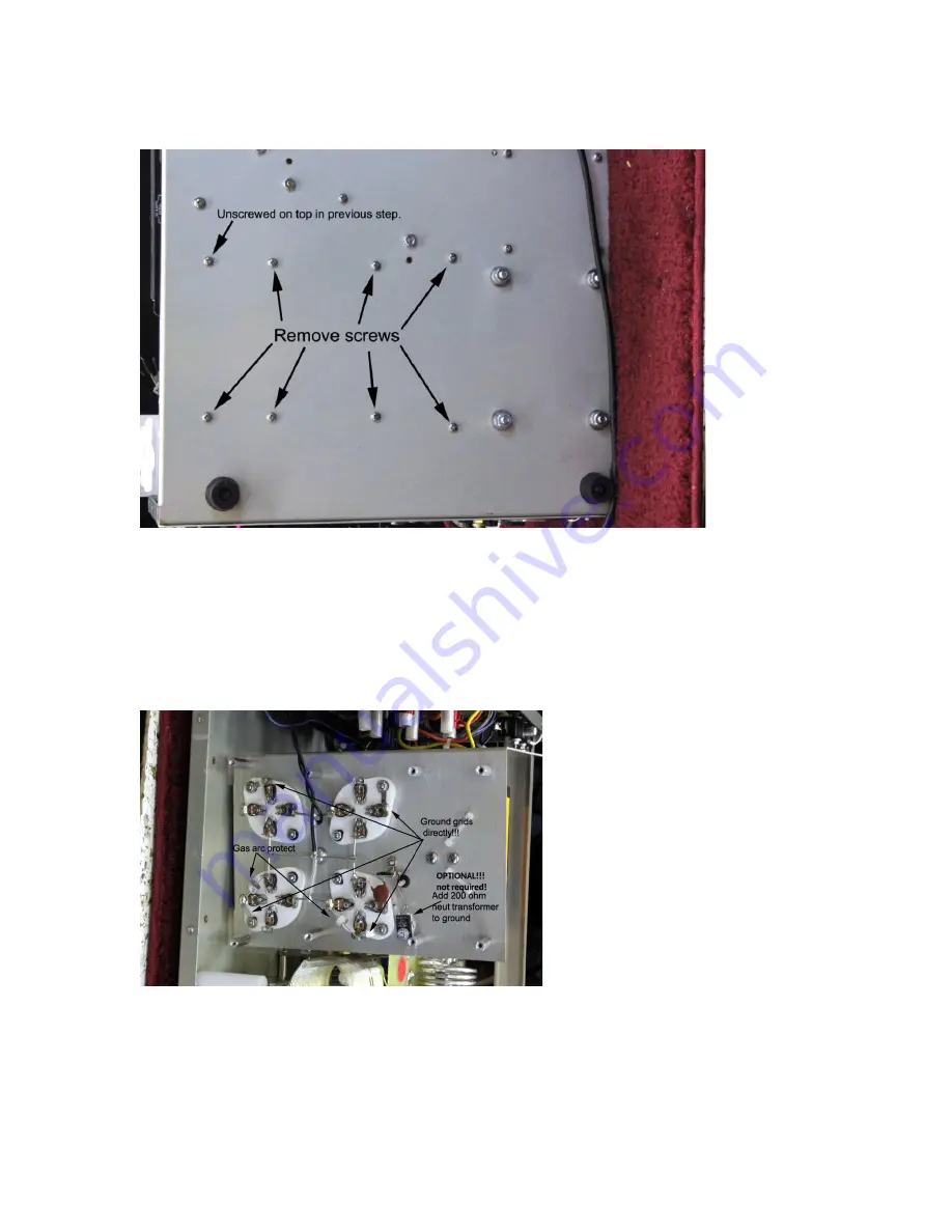
Flip the unit carefully on its side and remove the following screws:
Figure 18 811H remove bottom screws
Lay amplifier down and maneuver tube chassis to reach all sockets. Depending on wiring, the filament leads or
red HV choke lead could require removal. The filament leads are supposed to be loosely twisted as in Fig 18.
The
optional
200-ohm 25-watt resistor requires drilling a #4 clearance hole, deburring the hole, and using
heatsink compound and proper hardware (4-40 machine screw with lock washer and nut) to mount the
resistor. The resistor connects across the neutralizing capacitor. Fig. 19 Ground the tube grids directly using
solder lugs provided in the kit and solder the GDT’s in Fig. 18.
Figure 19 add GDTs AL811H only (811 was fig 4)
Check all the solder connections carefully. Inspect the plate choke. If the plate choke has loose or overlapped
wires it needs to be put back in a single tight wrap and
“re
-
glued”. Q
-dope can be made from a mix of lacquer
thinner or Xylene and pure white Styrofoam
“peanuts” used for packing. Dissolve the white packing peanuts


