background image


78 


Summary of Contents for SHRM03b TDM Series

Page 1: ...SHRM03b G SHDSL bis TDM Series 4U 19 Chassis ...

Page 2: ......

Page 3: ...supports the entire G SHDSL bis TDM Rack card family SHRM03b SH shelf SHRM03b PW Power Module SHRM03b PD SHRM03b FAN Fan Assembly SHRM03b series TDM based G SHDSL bis Line card SHRM03b E1 G 703 E1 card SHRM03b V35 Data Communications Card SHRM03b ET100 Ethernet Bridge Card SHRM03b SNMP Management Card Version 0 9a draft Version 1 1 July 2010 Update Copyright 2009 2010 CTC Union Technologies Inc Al...

Page 4: ... injury or death that may be associated with such unintended or unauthorized use even if such claim alleges that CTC Union Technologies was negligent regarding the design or manufacture of said product TRADEMARKS Microsoft is a registered trademark of Microsoft Corp HyperTerminal is a registered trademark of Hilgraeve Inc WARNING This equipment has been tested and found to comply with the limits f...

Page 5: ...ion 28 2 4 LINE CARD REMOVAL REPLACEMENT 29 2 4 1 Installing a Line Card 29 2 4 2 Removing a Line Card 29 3 OPERATION 31 3 1 LOGIN PROCEDURE 31 3 2 OPERATION INTERFACE 33 3 3 WINDOW STRUCTURE 33 3 4 MENU DRIVEN INTERFACE COMMANDS 35 3 5 MAIN MENU 36 3 5 1 Menu Tree diagram 2 wire mode 37 3 5 2 Menu Tree diagram 4 wire mode 38 3 6 SETUP 39 3 6 1 Setup Local 39 3 6 2 Setup Remote 41 3 6 3 Shdsl 42 3...

Page 6: ... 103 4 4 4 Show Card Status 106 4 4 5 System Info 107 4 4 6 Upgrade 108 4 4 7 Channel Setup 108 4 4 8 Channel Diagnostic 109 4 5 WEB BASED OPERATION MODE 110 4 5 1 Introduction 110 4 5 2 Web Login 110 4 5 3 Chassis View 111 4 5 4 Status 111 4 5 5 Configuration 112 4 5 6 Card Info 114 4 5 7 System Info 114 4 5 8 Performance 118 4 6 PROBLEMS AND SOLUTIONS 120 5 APPENDIX 122 5 1 CONSOLE CABLE 122 5 2...

Page 7: ...nectors are installed in the front of the chassis The power module for the SHRM03b series is including AC and DC input When AC input power is used the AC power cord is directly connected to rear side of the power module where it is rectified and regulated to 48VDC before routing to the backplane When DC input power is used the DC power cord is directly connected to rear side of the power module wh...

Page 8: ...y one pair with a maximum user data rate of 5 696Mbps for symmetric payload rates over exiting copper wire With using two pairs 4 wires operation uses single channel with a maximum user data rate of 11 392Mbps for symmetric payload rates over exiting copper wires One console port on the front panel of each line card Bandwidth guaranteed transmission equipment Remote line loopback SHDSL Line and E1...

Page 9: ...31 PCM31C and Unframed Data Rate 64Kbps to 2 048Mbps Nx64Kbps N 1 to 32 Operation Full E1 and Fractional E1 Serial Interface as RS 530 V 35 X 21 Connector DB 25 female for V 35 cable Payload rates Up to 5 696Mbps for 2 wire model or Up to 8 192Mbps for 4 wire model Support V 35 RS 530 or V 36 X 21 LAN Interface as Ethernet Connector RJ 45 Ethernet Interface 10 100Mpbs Half Full Duplex Auto sensing...

Page 10: ... Loopback Far end Payload Loopback V 54 Loopback for V 35 interface Build in 2047 211 1 bit BER tester Indicators Power PWR System SYS SHDSL bis Link SHDSL E1 T1 Interface status LOS LOF AIS V 35 Interface status TD RD CTS Ethernet Interface status LINK ACT 100M DUPX Diagnostic status TEST Error status ERROR Alarm Status ALARM Console ports One console ports on front panel for each cards Product s...

Page 11: ...6 72 V Power Card SHRM03b PD DC 36 72 V Power Card SHRM03b FAN Fan module SHRM03b SNMP SNMP card SHRM03b E1 SHDSL Bis TDM 2W 2Ch 4W 1CH E1 card SHRM03b V35 SHDSL Bis TDM 2W 2Ch 4W 1CH V 35 card SHRM03b ET100 SHDSL Bis TDM 2W 2Ch 4W 1CH ETHERNET card SHRM03b T1 SHDSL Bis TDM 2W 2Ch 4W 1CH T1 card ...

Page 12: ...12 Default Username and Password System User Name Password IP SNMP WEB SNMP Telnet SNMP Console Line card Console root admin cli admin root not need cli admin 192 168 0 1 192 168 0 1 ...

Page 13: ...t Panel 1 4 1 Slot Number Each slot will have a number from 1 to 15 indicating the slot number location of the right top side of each line cards From the front view of the chassis the numbers go from left to right ...

Page 14: ...14 1 4 2 Line card 1 4 2 1 View of Front Panel on Line Card SHRM03bB SHRM03b V35 SHRM03b ET100 SHRM03b T1 E1 interface V 35 interface Ethernet interface T1 interface ...

Page 15: ... No data transmit in V 35 Blink Received data in V 35 RD Green Off No data received in V 35 On CTS signal is On V 35 Interface status CTS Green Off CTS signal is Off On LAN port connected Blink Transmit or received data over Ethernet LINK ACT Green Off LAN port is disconnected On LAN port connect with 100M NIC 100M Green Off LAN port acts in 100M On LAN port is Duplex mode Ethernet Interface statu...

Page 16: ... Connector The front panel of each line card provides an RJ 45 connector for configuration individually from each channel of each line cards The terminal settings are 115200 8 bit no parity 1 stop bit and no flow control ...

Page 17: ... Front Panel on Power Supply Module 1 4 3 2 LED Indicators LED status of Power Supply Module LEDs Active Description On AC input is be used AC Off AC input isn t be used or no AC input On DC input is be used DC Off DC input isn t be used or no DC ...

Page 18: ... rear penal of each line card From the rear view of the chassis the numbers go from right to left 1 5 2 View of Rear Panel on Line card The rear panel provides all of the data connections for each line card A total of 15 slots are available for SHDSL bis TDM based Line Card The following is a description of all the connectors for the line cards located on the rear panel ...

Page 19: ...Interface SHRM03b T1 T1 Interface SHRM03b V35 V 35 Interface SHRM03b ET100 Ethernet Interface 1 5 2 1 DSL connector Use 4 pins wire wrap pin header provided the DSL twisted pair wire connect to the remote CPE device ...

Page 20: ...re two pins labeled T Tip and R Ring on channel A and channel B 4 wire mode 1 channel per card When using 4 wires Two pair mode the label A and B means 1st pair and 2nd pair of DSL wiring 1 5 2 2 E1 Interface Connector User can using one of the connector type of the following ...

Page 21: ...ector Transmit Tip Center pin of Tx Connector 5 Transmit Ring Shield of Tx Connector 4 Receive Tip Center pin of Rx Connector 2 Receive Ring Shield of Rx Connector 1 It is support dual jacks of BNC 75 ohms and RJ 45 120 ohms When using 4 wire 2 pairs mode only the upper side of E1 T1 connector can be used 1 5 2 3 Serial Interface connector ...

Page 22: ...minal Equipment connector is using 34 pin Winchester type we must use the cable adaptor from DB 25 to Winchester M 34 If there is X 21 application we must use the DB 25 to DB 15 adaptor cable When using 4 wire 2 pairs mode only the upper side of DB 25 F connector can be used 1 5 2 4 Ethernet Interface connector On the rear panel of Ethernet Interface Line card there have two RJ 45 connectors provi...

Page 23: ...23 When using 4 wire 2 pairs mode only the upper side of RJ 45 connector can be used ...

Page 24: ...ules can be using on AC or DC operation as the chassis backplane is designed for 48VDC direct connection to central office power 1 5 3 1 Power receptacle This is an IEC Connector To connect the AC power to the chassis insert the female end of power card to the power receptacle on the rear panel Connect the other end of the supplied power card to a 100 240V AC power outlet 1 5 3 2 Power Switch Ther...

Page 25: ...strip provides hard wired connections for DC power 48VDC to the FAN modules The size of the screws in the terminal block is M3 0 1 5 3 5 DC Power input connector This terminal strip provides hard wired connections for DC power 48VDC to the power service input WARNING Proper polarity must be observed for DC power connections or severe electrical damage may occur to the chassis Always confirm the po...

Page 26: ... carton for any shipping damage and report immediately to your freight forwarder if any damage is visible Step 2 Place the shipping carton with the top facing up Carefully cut through the shipping tape with a box cutter knife Step 3 Open the top cover of the carton and remove any pizza box Step 4 Pull the entire chassis straight up out of the carton Step 5 The chassis should be wrapped in a plasti...

Page 27: ... the process for the rack mounting bracket on the other side of the chassis Step 4 You may now mount the chassis on a rack Proceed to the next section 2 3 2 Mounting the chassis on a Rack Precautions a Make sure the rack will safely support the combined weight of all the equipment it contains b Make sure the position of the chassis doesn t make the rack unstable or top heavy Take all necessary pre...

Page 28: ...amage to the chassis and line cards as well has pose a serious safety hazard resulting in bodily injury to the installation personnel Only trained and qualified personnel should be allowed to install replace or service this equipment 2 3 3 AC power Connection To connect the AC power supply is perform the following 1 Using the supplied standard power cable with safety grounding connector connect th...

Page 29: ...rd in the main chassis Step 1 Using either an anti static grounded wrist strap or touching a grounded metal frame remove the line card from its anti static protective bag by grasping the metal panel Do not touch the PCB or components on the PCB Step 2 While still grasping the center of the front panel of the card with one hand place the other hand under the card to support it Step 3 Slide the Line...

Page 30: ...s and pull evenly on both to release the backplane connectors Step 3 After you have the card partially out of the chassis place one hand under the card to support it Step 4 Slide the card completely out of the slot and place in an anti static protective bag ...

Page 31: ...ning a terminal emulation application connected to the front panel CONSOLE port Windows includes a terminal emulation program called HyperTerminal Connect the appropriated communication port from the PC to this device After the physical connection is made you are ready to configure this product Make sure you have connected the supplied RS 232C serial cable DB9F to RJ 45 Plug to the console port on...

Page 32: ...ine card on your connection The card IDs are from 1 to 15 Press the SPACE key when the first screen appears it can enter to login screen When you see the login screen you can logon to device Username use admin When the system prompts you for a password type admin to enter is O K ...

Page 33: ...en interface In the menu you scroll up down by pressing key I K select one command by key L and go back to a higher level of menu by key J For example to show the system information just logon to the line card move down the cursor by pressing key K twice and select show command by key L you shall see a submenu and select system command in this submenu then the system will show you the general info...

Page 34: ...u field Menu tree prompts on this field Symbol indicates the cursor place 3 Configuring field You will configure the parameters in this field parameters indicates the parameters you can choose and more indicates that there have submenu in the title 4 Operational key in command list for your reference ...

Page 35: ...ove to bottom field in the same level menu LEFT or J Move back to previous menu RIGHT or L Move forward to submenu ENTER Move forward to submenu TAB To choose another parameters Ctrl C To quit the configuring item After you have some necessary setting for line card if may show Message Done Reboot needed You must make sure to write the new configuration to NVRAM by reboot command and then reboot th...

Page 36: ...fault setting Status Use this menu to show SHDSL status E1 V 35 Ethernet T1 status and statistics or clear the statistics Show Use this menu to show general information all configurations and all configurations in command script Reboot Use this menu to reset and reboot the system Diag Use this menu to setup diagnostic utility Upgrade Use this menu to upgrade the firmware kernel and FPGA code Exit ...

Page 37: ...37 3 5 1 Menu Tree diagram 2 wire mode ...

Page 38: ...38 3 5 2 Menu Tree diagram 4 wire mode ...

Page 39: ...n enter the setup sub menu by placing the cursor on the setup menu item and pressing the right arrow key or the ENTER key 3 6 1 Setup Local For 1 pair 2 wire mode When using 2 wires one pair configuration the line card has two separate channels A and B ...

Page 40: ...40 When enter the channel A or B you can view the left top side shows CH A or CH B For 2 pair 4 wire mode When using 4 wires two pair configuration the line card has only one channel ...

Page 41: ... left top side shows CH A 3 6 2 Setup Remote If the Line card has connected to remote side it can make a setup remote operation Following diagram show SHRM03b V35 Serial interface Line card connect to two 5010B Serial interface NTU The line card use 2 wire mode ...

Page 42: ... SHDSL setting including Mode Annex Psd Margin and Pair mode 3 6 3 1 Mode The mode of SHDSL bis refers to the clock and the clock setting of the line card The settings for the line card are for either internal clock STU C INTCLK or recovery clock STU C EXTCLK STU C INTCLK Where the clock source is set to internal ...

Page 43: ...uld be STU C INTCLK Ethernet interface line card SHRM03b ET100 Since Ethernet does not provide a clock the correct setting for this line card should always be STU C INTCLK T1 interface line card SHRM03b T1 When connecting this equipment to G 703 T1 transmission equipment the normal clock setting should be to take the T1 network timing In this case the correct setting for this line card should be S...

Page 44: ...44 3 6 3 3 Psd There are two type of PSD mask can select SYM and for ASYM The preferred and default setting is SYM ...

Page 45: ...can see the actual SNR margin in STATUS SHDSL The larger the SNR margin the better the line connection If you set the SNR margin in the setting field as 3 the SHDSL bis connection will drop and reconnect when the SNR margin is lower than 3 This will allow the device to reduce the line rate if rate adaptive setting is active and reconnect for a better line connection ...

Page 46: ...6 3 5 Pair Mode You can select one pair or two pair mode SHDSL parameter setting SETUP SHDSL Selection items MODE STU C INTCLK STU C EXTCLK ANNEX A B F G PSD SYM ASYM MARGIN 10 to 21 PAIR MODE 1 Pair 2 Pair ...

Page 47: ...C FAS CRC4 PCM30 FAS CAS PCM30C FAS CAS CRC4 FULL Unframed FAS Frame Alignment Signal uses a 7 bits pattern to establish and maintain the frame synchronization The FAS word is located in timeslot 0 of frame In FAS mode there are 1 31 timeslot available for use data CAS Also known as time slot 16 multi framing It requires a multi framing alignment signal to be present for frame sync The Multi frame...

Page 48: ...ng is to utilize the full bandwidth of the E1 line 0 1 2 3 4 5 6 7 8 31 Time Slots 64k 64k 64k 64k 64k 64k 64k 64k 64k 64k 1408k 9 30 Maximun Data Rate 2048kbps ITU 991 2 2004 G SHDSL Bis supports data rate up to 5696Kbps but G 703 E1 standard only supports data rate of 2048kbps so the maximum data rate of SHDSL line connected with E1 DCEs depends on data rate of E1 2048kbps STU C E1 STU R E1 DTE ...

Page 49: ... FAS CRC4 there are 1 31 available time slot for use data For example if the data rate of SHDSL line set to be 512k the time slot number is 8 and first time slot number is 1 The frame is shown as below FAS Data Data Data Data Data Data Data Data 0 1 2 3 4 5 6 7 8 31 Time Slots 64k 64k 64k 64k 64k 64k 64k 64k 64k 64k 1408k 9 30 The First Time Slot setting of PCM31 FAS and PCM31C FAS CRC4 have to fo...

Page 50: ... line codings HDB3 is the most popular and preferred line coding and is also the default setting AMI line coding is also selectable HDB3 In this line coding the transmitter substitutes a deliberate bipolar violation when excessive zeros in the data stream are detected The receiver recognizes these special violations and decodes them as zeros This method enables the network to minimize pulse densit...

Page 51: ...testing with AIS When enabled the E1 will transmit the AIS and it should be confirmed at the remote device AIS indication lit After testing please turn AIS back off Example 1 When STU R E1 RX line is dropped STU R sends the status to STU C via EOC or command and then STU C will send AIS Alarm Indication Signal to DTE while AIS function is enabled Example 2 When SHDSL connection drops STU R and STU...

Page 52: ...52 75 Ohms 120 Ohms BNC Connector RJ 45 Connector ...

Page 53: ...CM31 FAS 1 to 31 1 to 31 PCM31C FAS CRC4 1 to 31 1 to 31 PCM30 FAS CAS 1 to 30 1 to 31 cannot use 16 PCM30C FAS CAS CRC4 1 to 30 1 to 31 cannot use 16 FULL UNFRAMED 3 6 5 Setup Serial interface The serial settings include the interface mode data rate clocking and handshaking lines setup 3 6 5 1 Interface The serial line card supports both V 35 interface and RS 530 X 21 interface ...

Page 54: ...nnex F and G the rate can be adjusted in increments of 64kbps from 64kbps to 5696kbps N 1 89 For 4 wires with Annex A and B the rate can be adjusted in increments of 64kbps from 128kbps to 4608kbps N 2 72 even number only For 4 wires with Annex F and G the rate can be adjusted in increments of 64kbps from 128kbps to 8192kbps N 2 128 even number only ...

Page 55: ...usted to solve some clocking issues The default setting is Normal clock polarity where data is sent on the positive transition of the clock while the option exists to set inverse clock polarity where data is sent on the negative clock transition 3 6 5 4 Data ...

Page 56: ...le the option exists to set inverse data polarity where data is sent on the positive transition 3 6 5 5 Rts The behavior of the RTS Request To Send signal may be set in one of two ways When set on the RTS signal is always forced high on positive voltage or SPACE when set from dte the RTS signal will follow the DTE s condition The default setting for RTS is from DTE ...

Page 57: ... ways When set on the CTS signal is always forced high on positive voltage or SPACE when set off the signal is always forced low off negative voltage or MARK or CTS will follow RTS Request To Send condition of on for RTS on or off for RTS off The default setting for CTS is to follow RTS ...

Page 58: ...l Ready condition of on for DTR on or off for DTR off The default setting for DSR is to follow DTR 3 6 5 8 Dcd The behavior of the DCD Data Carrier Detect signal may be set in one of three ways When set on the DCD signal is always forced high on positive voltage or SPACE when set off the signal is always forced low off negative voltage or MARK or DCD will follow the DSL condition of on for DSL lin...

Page 59: ...59 ...

Page 60: ...ard SHRM03b V35 The below diagram shows CTS follow RTS DSR follow DTR V 35 Interface Line Card SHRM03b V35 3 6 5 9 Delay The delay setting is used to cause a delay for CTS to follow RTS The delay setting may be set from 0 to 3 milliseconds The default setting is 3 milliseconds ...

Page 61: ... for the setting CTS follow RTS and RTS follow from DTE V 35 Interface control signals settings table Serial Items Setting INTERFACE V 35 X 21 RS 530 Annex A B 1 36 2 wires Annex F G 1 89 Annex A B 2 72 even number only DATA RATE Nx64K mode 4 wires Annex F G 2 128 even number only ...

Page 62: ...A Normal Inverse RTS On From DTE CTS On Off From RTS DSR On Off From DTR DCD On Off From DSL DELAY 0mS 1mS 2mS 3mS 3 6 6 Setup Ethernet interface The Ethernet settings include the data rate negotiation duplex the speed Date Rate ...

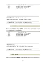
Page 63: ...of 64kbps from 64kbps to 5696kbps N 1 89 For 4 wires with Annex A and B the rate can be adjusted in increments of 64kbps from 128kbps to 4608kbps N 2 72 even number only For 4 wires with Annex F and G the rate can be adjusted in increments of 64kbps from 128kbps to 11392kbps N 2 178 even number only 3 6 6 1 Negotiation You can select Enable and Disable on auto negotiation function I ...

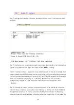
Page 64: ... 2 Duplex When auto negotiation setup is Disable there has to be a selection of duplex mode Full Duplex and Half Duplex 3 6 6 3 Speed When auto negotiation is Disable there has to be selection on speed setting ...

Page 65: ... is Full and Speed is 100M If you set Ethernet Auto Negotiation as Enable the Duplex and Speed cannot be set up and it will use auto configuration Ethernet parameter setting Ethernet Items Setting Annex A B 1 36 2 wire s Annex F G 1 89 Annex A B 2 72 even number only Rat e 4 wire s Annex F G 2 178 even number only Auto Disable Enable Duplex Full Duplex Half Duplex Auto Configuration Speed 100M 10M...

Page 66: ...ond to maintain those 24 simultaneous voice channels Because each frame of a T1 is 193 bits in length 24 channels X 8 bits per channel 1 framing bit 193 bits 8000 frames per second is multiplied by 193 bits to yield a transfer rate of 1 544 Mbit s 8000 X 193 1544000 The T1 format provides a 64 Kbps channel for each of 24 individual channels Each of these channels is called a DS 0 channel or a time...

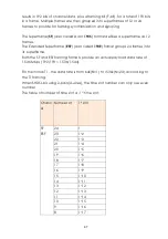
Page 67: ...lled 193E format groups 24 frames into its superframe Both the SF and ESF framing formats provide an actual payload data rate of 1 536 Mbps 192 193 1 536 1 544 For fractional T1 the data rate is from 64k N 1 to 1536k N 24 according to the T1 framing When SHDSL bis using 2 pairs 4 wires the time slot number can only use even number The table of number of time slot vs 1st time slot Chann el Number o...

Page 68: ... cable lengths between T1 device and NTU are vary LBO settings are designed to adjust the output power of the transmission signal to achieve equal level point ELP at the NTU For short distance of T1 cable this device must decreases outgoing signal strength There are five type T1 LBO for your select 0 133ft 133 266ft 266 399 ft 399 ft 533ft 533ft 655ft 3 6 7 3 AIS ...

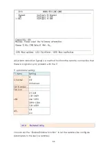
Page 69: ...sync problem with the T1 T1 parameter setting T1 items Setting Channel SF ESF Unframed Slot Number First Slot LBO 0 133ft 133 266ft 266 399ft 399ft 533ft 533 655ft AIS Off On 3 6 8 Remote Config You can set the Enable Disable function to let the remote side configure parameters to this device remotely ...

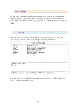
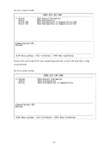
Page 70: ...ault item and then press ENTER The system will ask for a y es or n o confirmation followed by an ENTER 3 7 Status From the main setup menu after logging in arrow key down to select the status menu item and then press the right arrow key or ENTER From the main Status Display menu press the right arrow or ENTER when the cursor is on the shdsl menu item ...

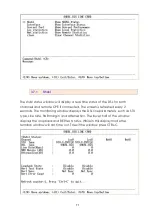
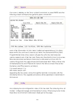
Page 71: ...nected The screen is refreshed every 2 seconds The monitoring window displays the DSL line parameters such as STU type Line rate SNR margin and attenuation The lower half of the window displays the loopback and BER test status While in this display mode the terminal window will not time out To exit the window press CTRL C ...

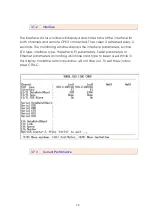
Page 72: ...en is refreshed every 2 seconds The monitoring window displays the interface parameters such as STU type interface type there have E1 parameters Serial parameters or Ethernet parameters according which line card type to been used While in this display mode the terminal window will not time out To exit the window press CTRL C 3 7 3 Current Performance ...

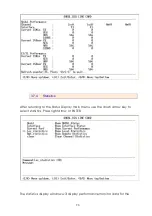
Page 73: ... 4 Statistics After returning to the Status Display main menu use the down arrow key to select statistics Press right arrow or ENTER The statistics display window will display performance monitor data for the ...

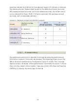
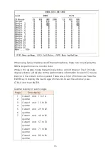
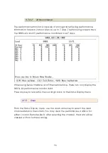
Page 74: ...ics support ES SES UAS LOSW E1 statistics support ES SES UAS SHRM03bB E1 interface SHRM03b V35 Series interface SHRM03b ET100 Ethernet interface SHRM03b T1 T1 interface 3 7 4 1 15 minutes interval The performance monitor is capable of storing and retrieving performance information for each 15 minute one quarter The following screen shows the SHDSL bis and E1 performance monitored on each 15 minute...

Page 75: ...r each 15 minute interval in the current 24 hour period There are a total of 96 intervals Press the ENTER key to display the next page of intervals To exit the window press CTRL C and then ENTER Quarter display on each page Page Time display 1 2 3 4 5 6 7 Current and 1 to 14 quarter Current and 15 to 28 quarter Current and 29 to 42 quarter Current and 43 to 56 quarter Current and 57 to 70 quarter ...

Page 76: ...sing Series Interface and Ethernet Interface there can only display the SHDSL bis performance monitor data Press any key to leave this menu and go back to the Status Display menu 3 7 5 Clear From the Status Display menu use the down arrow key to select the clear channel statistics menu item You may clear the performance statistics for either Local or Remote side B After selecting the channel the d...

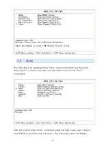
Page 77: ... Show menu command Use the down menu key K or down cursor key and place the cursor on the show command With the cursor on the show command press the right cursor key J key or press ENTER to go to the next sub menu The following screen will display ...

Page 78: ...78 ...

Page 79: ...79 For two wires mode Script Ch0 and script Ch1 are meaning channel A and channel B by using script format For four wires mode ...

Page 80: ...ailable in the future to add extra functions of to fix unknown bugs from the original manufactured equipment Please make note of the Kernel MCSV and FPGA MCSV items in the above screen These show the Kernel and FPGA versions as follows 114 means version 1 14 009 means version 0 09 Upgrading the line cards is done through the terminal connection with the Xmodem protocol The upgrade procedure will b...

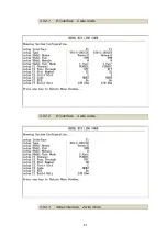
Page 81: ...81 3 8 2 1 E1 interface 2 wire mode 3 8 2 2 E1 interface 4 wire mode 3 8 2 3 Series interface 2 wire mode ...

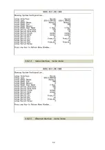
Page 82: ...82 3 8 2 4 Series interface 4 wire mode 3 8 2 5 Ethernet interface 2 wire mode ...

Page 83: ...83 3 8 2 6 Ethernet interface 4 wire mode ...

Page 84: ...84 3 8 2 7 T1 interface 2 wire mode 3 8 2 8 T1 interface 4 wire mode ...

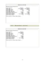
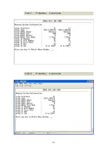
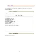
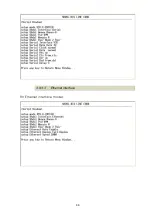
Page 85: ... 3 8 3 Script It can display the all configuration value of this line card with using Script command format 3 8 3 1 E1 interface For E1 interface model 3 8 3 2 Serial interface For Serial interface model ...

Page 86: ...86 3 8 3 3 Ethernet interface For Ethernet interface model ...

Page 87: ...87 3 8 3 4 T1 interface For T1 interface model ...

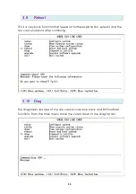
Page 88: ...hat needs no further explanation select it and the line card will reboot after confirming 3 10 Diag The diagnostics features of the line card include loop back and Bit Error Rate functions From the main menu move the cursor down to the diag option ...

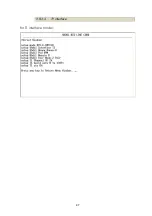
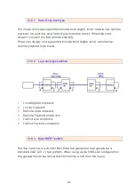
Page 89: ...igital local remote line remote payload loop backs 3 10 2 Loop back types defined 1 Local Digital Loopback 2 Local Loopback 3 Remote Line Loopback 4 Remote Payload Loopback 5 Far End Line Loopback 6 Far End Payload Loopback 3 10 3 Select BERT pattern The line card has a built in Bit Error Rate Test generator that generates a standard 2047 211 1 test pattern When using 2 wire SHDSL bis configuratio...

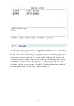
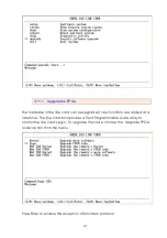
Page 90: ...e code without changing any components or removing cards Of course during upgrade and re flash the normal transmissions will be halted so the upgrade should be done when the system is taken offline or done during a time of extremely low impact to the customer s line like in the middle of the night The upgrade process uses the Xmodem protocol via the line card s serial console port ...

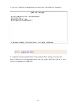
Page 91: ...pgrade if new functions are added at a later time The line card incorporates a Field Programmable Gate Array to control the line card s logic To upgrade the code choose the Upgrade FPGA code option from the menu Press Enter to enable the reception of Xmodem protocol ...

Page 92: ...send the file The binary file is uploaded to the RAM in the line card with CRC error checking provided by the Xmodem protocol Once the upload is complete all that is required is to make the final confirmation to erase and re write the flash with the new binary code WARNING Do not allow any interruption of power during the erase and re write operation or the Flash will be left in an unknown state a...

Page 93: ...be returned to the factory for repair 3 11 2 Upgrade the Kernel To upgrade the kernel software follow exactly the same procedure and select kernel from the upgrade menu Use the binary file for the kernel to send from the HyperTerminal window ...

Page 94: ...94 3 12 Exit To exit the console configuration mode cursor down to exit and press Enter Answer y es to confirm ...

Page 95: ...rnet LAN port of SNMP card 3 Web based mode Configuration by 10 100 Ethernet LAN port of SNMP card CTC Union s network management systems support various important functions 1 Fault management correlates fault management data from all network devices isolates faults and initiates recovery actions 2 Configuration management 3 Performance management Features View which type of cards occupy the chass...

Page 96: ... the NMS Hardware RJ 45 to DB 9 F Console cable RJ 45 to RJ 45 Ethernet Cable Required for establishing a direct connection from the SNMP card of rack mount shelf to a web server Software Hyper Terminal Telnet Web Browser IE etc 4 1 2 View of front Panel on SNMP card ...

Page 97: ...e status 100M Green Off LAN port acts in 10M or LAN port is no connect ACO Alarm Cut Off When alarm status is active audible and visuable alarm output are On If the user want to turn off the audio alarm please press the ACO SW bottom It will turn ACO LED off and turn audible alarm off Aud Audible Alarm Output If there are alarm triggered and ACO is inactive It will be turn the audible relay on oth...

Page 98: ...erminal port designed to facilitate setup of all parameters through the use of a standard text based terminal or any terminal emulation program running on a Personal Computer You can manage the Line Card locally by connecting the console port to a PC or workstation with terminal emulation software After the physical connection is made you are ready to configure the SNMP Card Make sure you have con...

Page 99: ...r PC is set to Full Duplex Using a straight through or cross over Ethernet cable connect your PC to the Ethernet RJ45 management port on the front of the LAN connector of SNMP card The LINK LED will illuminate green to indicate an Ethernet connection has been established 4 2 1 3 Web based mode Configuration by LAN port of SNMP card by Web browser The Ethernet cable connection like as above Configu...

Page 100: ...ulation VT 100 compatible Band rate 115200 Data bits 8 Parity None Stop Bits 1 Flow Control None The main menu Their display screen are same as Telnet mode Please refer to the chapter of Telnet operation mode ...

Page 101: ...nel shall light if a correct cable is used Starting your Telnet client with VT100 terminal emulation and connecting to the management of SNMP wait for the login prompt appears Input User and Password after login screen pop up The default username is admin When password request press ENTER key 4 4 1 Main menu The NMS main window appears upon login ...

Page 102: ...g 1 Card Info 2 Show Card Configuration 3 Show Card Status 4 System Info 5 Upgrade 6 Channel Setup 7 Channel Diagnostic 0 Exit 4 4 2 Card Info The slots available number shows on top side meaning which slots of line card have installed ...

Page 103: ...ID SHRM03b E1 3300 SHRM03b V35 3310 SHRM03b ET100 3320 SHRM03b T1 3305 SHDSL bis NTU Series SHDSL bis NTU Series SHDSL bis NTU Series SHDSL bis NTU Series Model name Model number Product ID SHDTU03b AC 2W E1 SHDTU03b DC 2W E1 SHDTU03b DA 2W E1 5000B 5300 SHDTU03b AC 2W SER SHDTU03b DC 2W SER SHDTU03b DA 2W SER 5010B 5310 SHDTU03b AC 2W ETH SHDTU03b DC 2W ETH 5020B 5320 ...

Page 104: ... SHDTU03b AC 4W ETH SHDTU03b DC 4W ETH SHDTU03b DA 4W ETH 5021B 5325 SHDTU03b AC 4W E1 T1 SHDTU03b DC 4W E1 T1 SHDTU03b DA 4W E1 T1 5007B 5306 SHDTU03b AC 4W E1 SER ETH SHDTU03b DC 4W E1 SER ETH SHDTU03b DA 4W E1 SER ETH 5031B 5335 SHDTU03b AC 4W E1 T1 SER ETH SHDTU03b DC 4W E1 T1 SER ETH SHDTU03b DA 4W E1 T1 SER ETH 5037B 5337 The display is same as following table Subject Items Local side Channe...

Page 105: ...105 Ethernet Rate Auto Speed Duplex ...

Page 106: ...Items Local side Channel A Local side Channel B Remote side Channel A Remote side Channel B Cards usage Model Interface SHDSL bis Type Shdsl Link Rate SNR Margin Attenuation E1 Rate Channel TS First TS Serial Serial Rate DSR DCD RTS CTS DTR Ethernet Eth Rate Link Speed Duplex ...

Page 107: ...107 4 4 5 System Info There have three basic setting on this menu 1 IP Setup 2 Gateway Setup 3 Time and Date Setup Power card status 4 Power status ...

Page 108: ...le name 3 Type 2 for SNMP card upgrade For Line Cards upgrade type the following steps 1 Type 2 for setup TFTP IP 2 Type 4 for setup upgrade file name 3 Type 1 for line card upgrade 4 Select which slot number to upgrade 5 Select which channel 1 local side 2 remote side channel A 3 remote side channel B 4 4 7 Channel Setup ...

Page 109: ...Channel 1 and 2 are means local side channel A and channel B Channel 3 and 4 are means remote side channel A and channel B 4 4 8 Channel Diagnostic Channel Diagnostic Slot Number Select Channel Loopback Disable Local Digital Local Rmt Line Rmt Payload ...

Page 110: ... console the unit can be accessed via TCP IP using Telnet SNMP or HTTP web browser In the address bar of the web browser enter http and the IP address of the SNMP agent 4 5 2 Web Login For security the web based management requires a username and password to login The default username is root and the password is root the user level console terminal password When enter the system you can view the m...

Page 111: ...ll line cards is shown in real time Using the browser interface open the top menu by clicking the Chassis View and then clicking on the line card number you selected You can view the channel A and B and both the CO central and RT remote devices status Click the Set button to setup the Page Refresh Time 4 5 4 Status Clicking the Status button and then selecting the appropriate line card number a st...

Page 112: ...uration By selecting the appropriate line card number then clicking the Configuration button a configuration selection will be displayed The current values are shown each parameter has a pull down to select the available settings for that parameter When all the parameter values are set to your liking click the Save button and the values will be set in the line card or NTU ...

Page 113: ...113 side Click Reset button and the values will be set to default ...

Page 114: ...are information of each card 4 5 7 System Info This item is including system information SNMP Line card upgrade diagnostic etc 4 5 7 1 Common This item show system information of SNMP card user can also setup the parameter for SNMP card on here ...

Page 115: ...tion to upgrade the firmware on SNMP card 4 5 7 3 Line card Upgrade Use this function to upgrade the firmware on each line card Local side and remote side NTU User can also view the present version of firmware on these line cards and those NTUs ...

Page 116: ...116 4 5 7 4 SNMP All SNMP parameter must setup on this item ...

Page 117: ...gnostic 1 Local Digital Loopback 2 Local Loopback 3 Remote Line Loopback 4 Remote Payload Loopback 5 Far End Line Loopback 6 Far End Payload Loopback 4 5 7 6 User By this item user can modify the username and password ...

Page 118: ... view The time interval used 15 minute and 24 hour one days The items include 15 minute interval SHDSL data for Line card and NTU INTERFACE data for Line card and NTU for E1 and T1 interface only 24 hour interval SHDSL data for Line card and NTU INTERFACE data for Line card and NTU for E1 and T1 interface only ...

Page 119: ...ata support SHRM03bB SHRM03b V35 SHRM03b ET100 SHRM03b T1 15 min SHDSL line card 15 min SHDSL NTU 15 min INTERFACE line card 15 min INTERFACE NTU 24 hr SHDSL line card 24 hr SHDSL NTU 24 hr INTERFACE line card 24 hr INTERFACE NTU ...

Page 120: ...ll return a list of all the IP Addresses in the computer s ARP cache 5 If the IP address you wish to clear is listed type arp d the IP Address at the prompt and press the Enter key Web Pages Are Loading Slowly If NMS pages are accessible but refreshing slowly close all browser windows and re launch the application If the problem continues you may be encountering one of the following conditions 1 T...

Page 121: ...twork Congestion Extensive network congestion may impact NMS performance due to the fact that the embedded web server powering NMS is a TCP IP device Under heavy congestion you will notice most other network tasks experiencing a slowdown as well ...

Page 122: ...J 45 console cable socket on front panel The wire connection of console cable DB 9 Female to RJ 45 DCD 1 RXD 2 TXD 3 DTR 4 GND 5 DSR 6 RTS 7 CTS 8 DSR 1 DCD 2 DTR 3 GND 4 RXD 5 TXD 6 CTS 7 RTS 8 NC 9 DB9 Female RJ 45 The signal direction of console cable ...

Page 123: ... console cable Pin Number Abbrev Description Figure 1 DSR DCE ready 2 DCD Received Line Signal Detector 3 DTR DTE ready 4 GND Signal Ground 5 RXD Received Data 6 TXD Transmitted Data 7 CTS Clear to Send 8 RTS Request to Send 1 8 1 8 Top View Front View ...

Page 124: ... 7 B 8 Data Carrier Detect DCD Output 8 F 5 Secondary Receiver Clock S RC Output 9 X 13 Secondary Data Carrier Detect S DCD Output 10 12 Secondary External Transmitter Clock S ETC Input 11 W 7 Secondary Transmitter Clock S TC Output 12 AA Secondary Clear to Send S CTS Output 13 Secondary Transmit Data S TD Input 14 S 9 Transmitter Clock TC Output 15 Y Secondary Receive Data S RD Output 16 T 11 Rec...

Page 125: ...125 Ready Secondary Data Terminal Ready S DTR Input 23 External Transmitter Clock ETC Input 24 U 14 Test Indicator 25 The front view of DB 25 F Serial interface connector on rear panel ...

Page 126: ...wist lock BNC connector The front view of BNC sockets on rear panel The internal wiring between BNC sockets and RJ 48C Signal Name BNC Connecters RJ 48C Connector Transmit Tip Center pin of Tx Connector 5 Transmit Ring Shield of Tx Connector 4 Receive Tip Center pin of Rx Connector 2 Receive Ring Shield of Rx Connector 1 ...

Page 127: ...20 DTR H Data Terminal Ready 24 XTC U DTE Transmit Clock 11 XTC W DTE Transmit Clock 15 TC Y Transmit Clock 12 TC AA Transmit Clock 17 RC V Receive Clock 9 RC X Receive Clock 1 FGND A Protective Ground 7 GND B Signal Ground 8 DCD F Data Carrier Detect V 35 is a partially balanced partially single ended interface specification The data leads and clock leads are balanced the handshake leads are sing...

Page 128: ...128 cable ...

Page 129: ... Unassigned L Unassigned M Unassigned N Unassigned P Send Data A SD A Out In R Receive Data A RD A In Out S Send Data B SD B Out In T Receive Data B RD B In Out U Terminal Timing A SCTE A Out In V Receive Timing A SCR A In Out W Terminal Timing B SCTE B Out In X Receive Timing B SCR B In Out Y Send Timing A SCT A In Out Z Unassigned AA Send Timing B SCT B In Out BB Unassigned CC Unassigned DD Unas...

Page 130: ...tive Ground 7 GND 8 Signal Ground 2 T 2 Transmit Data 14 T 9 Transmit Data 3 R 4 Receive Data 16 R 11 Receive Data 4 C 3 Request To Send 19 C 10 Request To Send 8 I 5 Data Carrier Detect 10 I 12 Data Carrier Detect 17 S 6 Receive Clock 9 S 13 Receive Clock All signals are balanced Meaning there is always a pair for each signal like used in RS422 The X 21 signals are the same as RS422 so please ref...

Page 131: ...131 ...

Page 132: ...TB Out In 10 Control B CB Out In 11 Receive B RB In Out 12 Indication B IB In Out 13 Signal Timing B SB In Out 14 Unassigned 15 Unassigned Functional Description The Signal Element Timing clock S is provided by the DCE This means that the NTU is output the correct clocking and that X 21 is a synchronous interface Hardware handshaking is done by the Control C and Indication I lines The Control is u...

Page 133: ...are supported by the auto crossover feature of the Line card We do not provide the cable It is widely available from other sources The front view of RJ 45 Ethernet cable socket on rear panel The pin out of RJ 45 Ethernet Connector Pin number Signal Name 1 2 3 4 5 6 7 8 Transmit Data Transmit Data Receive Date Not used Not used Receive Date Not used Not used ...

Page 134: ...8C Pin number Description 4 Transmit Ring 3 Rx Shield 1 Receive Ring 6 TX Shield 5 Transmit Tip 2 Receive Tip Make the short circuit wiring with a RJ 45 module jack of the following PIN1 PIN4 PIN2 PIN5 The top view of RJ 45 module jack on short circuit wiring ...

Page 135: ...Set Ready 20 DTR Data Terminal Ready 24 XTC DTE Transmit Clock 11 XTC DTE Transmit Clock 15 TC A Transmit Clock 12 TC B Transmit Clock 17 RC A Receive Clock 9 RC B Receive Clock 1 FGND Protective Ground 7 GND Signal Ground 8 DCD Data Carrier Detect Make the short circuit wiring with a DB 25 male connector of the following PIN2 PIN3 PIN14 PIN16 PIN4 PIN5 PIN6 PIN20 The back side view of DB 15 male ...

Page 136: ...136 ...

Page 137: ......

Page 138: ......

Reviews: