background image

Chapter 2. Port Card Overview 

12 

Version 1.2 Apr 2006


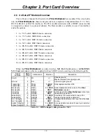
2.6  4 x Data I/F Module Overview 

The 4 x Data 4-Channel Port Cards for the 

Fiber Multiplexer 

are modular PCAs which slide 

into the 

Fiber Multiplexer 

chassis and provide four completely independent Data (V.35, X.21, 

RS-530, RS-449, or RS-232) interfaces. The PCA module terminates with a HD62F connector that 
is designed to connect to a physical adapter. The Data module is available in one of ten interface 
and cable options.  


1.   4 x V.35 with 4 MB34 Female connectors 

2.   4 x V.35 with 4 MB34 Male connectors 

3.   4 x X.21 with 4 DB15 Female connectors 

4.   4 x X.21 with 4 DB15 Male connectors 

5.   4 x RS-530 with 4 DB25 Female connectors 

6.   4 x RS-530 with 4 DB25 Male connectors 

7.   4 x RS-449 with 4 DB37 Female connectors 

8.   4 x RS-449 with 4 DB37 Male connectors 

9.   4 x RS-232 with 4 DB25 Female connectors 

10. 4 x RS-232 with 4 DB25 Male connectors 


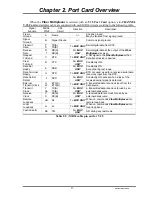
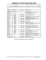
When the 

Fiber Multiplexer 

is ordered with an 

X21 Port Card

 option, a 

4-CHANNEL 

X.21 Card

 and adapter cable are supplied with each DB15 wired according to the following table.  

Signal 

Function 

DB15 

PIN# 

Abbreviation Direction 

Description 

Shield 1 

FG 

<-> 

Chassis ground. 
May be isolated from signal ground. 

Ground 

SG 

<-> 

Common signal ground. 

Transmit(A) 
Transmit(B) 


TD(A) 
TD(B) 

To 

MUX 

UNIT


Serial digital data from DTE. 
 

Receive(A) 
Receive(B) 

11 

RD(A) 
RD(B) 

Fm. 

MUX 

UNIT


Serial digital data at the output of the 

Fiber 

Multiplexer 

receiver. 

Control(A) 
Control(B) 

10 

RTS(A) 
RTS(B) 

To 

MUX 

UNIT


A ON signal to the 

Fiber Multiplexer 

when data 

transmission is desired. 

Indication(A) 
Indication(B) 

12 

DCD(A) 
DCD(B) 

Fm. 

MUX 

UNIT


Constantly ON, except when a loss of the 
received carrier signal is detected. 

Ext. Timing(A) 
Ext. Timing(B) 

14 

ETC(A) 
ETC(B) 

To 

MUX 

UNIT


A transmitted data rate clock input from the data 
source. 

Signal Timing(A) 
Signal Timing(B) 

13 

RC(A) 
RC(B) 

Fm. 

MUX 

UNIT


A received data rate clock for use by an external 
data source. 

Table 2-1 : DB15 adapter cable pin out for X.21 

Summary of Contents for FMUX-01A

Page 1: ...SER MANUAL FMUX 01A Fiber Optical Multiplexer Standalone Rack Type 4 8 12 or 16 Channel Modular Design G 703 E1 T1 DS1 Datacom V 35 X 21 RS 530 RS 449 RS 232 Ethernet 10 100Base TX Bridge SNMP Manageable ...

Page 2: ......

Page 3: ...intended or unauthorized use even if such claim alleges that CTC Union Technologies was negligent regarding the design or manufacture of said product TRADEMARKS Microsoft is a registered trademark of Microsoft Corp HyperTerminal is a registered trademark of Hilgraeve Inc WARNING This equipment has been tested and found to comply with the limits for a Class A digital device pursuant to Part 15 of t...

Page 4: ...rsion 1 0 Mar 2004 Released for first printing Version 1 1 July 2005 Added Datacom Loopback Timing Version 1 2 Apr 2006 This manual supports the following models FMUX 01A This document is the third official release manual Please check CTC Union s website for any updated manual or contact us by E mail at info ctcu com Please address any comments for improving this manual or to point out omissions o...

Page 5: ...ocedures 22 3 5 1 Optical Module Removal Replacement Hot Swappable 22 3 5 2 Channel Port I F Module Removal Replacement 23 3 5 3 Top cover Removal Replacement for internal access 24 3 5 4 External Clock Feature Removal Replacement 25 3 5 5 SNMP Feature Removal Replacement 26 Chapter 4 Operation 4 1 Introduction 27 4 2 LCD Menu Operation 27 4 2 1 Top Level Menus 28 4 2 2 Menu Table 30 4 3 Terminal ...

Page 6: ...ort Card Loop Back 45 5 2 4 Datacom RS 530 V 35 X 21 RS 449 RS 232 4 Channel Port Card Timing 46 Chapter 6 SNMP Operation 6 1 General 47 6 2 SNMP Operations 47 6 3 The Management Information Base 48 6 4 MIB Structure 48 6 5 SNMP Communities 49 6 6 Configuring the SNMP Agent 49 6 7 Configure the SNMP Manager 52 6 8 Save and Restart SNMP 52 6 9 SNMP Upgrade via TFTP 53 6 10 SNMP Object Details 53 6 ...

Page 7: ...Multiplexer basic chassis is available in five power supply configurations Depending on the model power may be derived from single AC 90 250VAC single DC 20 60VDC dual AC 90 250VAC dual DC 20 60VDC or AC plus DC power sources The Fiber Multiplexer provides all Line Card connections on the rear panel There are 4 slots available for installation of 4 CHANNEL E1 or T1 Port Cards ITU T G 703 E1 T1 4 C...

Page 8: ...hich is not tied to a fixed optical interface When two optical modules are installed the secondary module is in standby in case of any failure in the primary path If the primary fiber path fails the switchover time to the secondary fiber is less than 50 milliseconds industry standard The automatic fall over function of the fiber allows the fiber to continue to run in the secondary fiber even after...

Page 9: ...d d d A A A s s s s s s y y y S S SN N NM M MP P P C C Ca a ar r rd d d E E Ex x xt t te e er r rn n na a al l l C C Cl l lo o oc c ck k k O O Op p pt t ti i i 2 2 2 O O Op p pt t ti i i 1 1 1 F F F W W W The following photo with graphics shows the major components which make up the Fiber Multiplexer with the External Clock and SNMP options installed This photo shows a unit with E1 BNC card in por...

Page 10: ...oop Back RLB Remote Loop Back RRLB Request Remote Loop Back Transparent to framing ITU T G 704 transparent to ISDN PRI 30B 1D E1 transmissions T1 Link Framing Unframed transparent Bit Rate 1 544 Mb s Line Code AMI B8ZS Line Impedance Balanced 100 ohms RJ 45 Receiver sensitivity 3 to 12dB short haul Pulse Amplitude Nominal 3 00V 10 for 100 ohms Zero Amplitude 0 3V Transmit Frequency Tracking Intern...

Page 11: ...ws RTS DSR constantly ON except during test loops DCD constantly ON except during signal loss Test Loops LLB Local Loop Back RLB Remote Loop Back V 54 Bridge Port Channels Interface Type 10Base T 100Base TX auto negotiation Interface Connector RJ 45 WAN Data Rate 8 192Mb s Complies with IEEE802 3 10Base T IEEE802 3u 100Base TX Configuration modes bridge repeater full half 10 100 auto Test Loops NO...

Page 12: ...m Cutoff Amber Audible Alarm has sounded alarm cutoff switch has been pushed Minor Alarm Amber Indicates a minor alarm has occurred includes E1 or T1 BPV or fiber sync slip Major Alarm RED Indicates a major alarm has occurred includes E1 T1 and fiber signal loss Far End Error Amber Indicates a far end remote error has occurred Near End Error RED Indicates a near end local error has occurred System...

Page 13: ...er transceivers in the Multiplexer incorporate an automatic laser shutdown feature ALS designed to protect personnel that may come into contact with a disconnected fiber connection This feature may also be disabled for testing purposes via the front panel LCD console terminal mode or SNMP when SNMP option is installed The fiber module ports may be independently installed with any of the above fibe...

Page 14: ...pports only transparent unframed format ie The E1 will pass through with its original framing structure completely intact 1 5 T1 DS1 Signal Structure T1 link line rate The T1 line operates at a nominal rate of 1 544Mb s T1 link line coding The basic T1 line signal is coded using either the Alternate Mark Inversion AMI or B8ZS rule In the AMI format ones are alternately transmitted as positive and ...

Page 15: ...cheme for typical E1 or T1 equipment is to transparently pass timing from a timing source unit on one side to a timing slaved unit on the other Each of the up to 16 available channels of the Fiber Multiplexer is independent of any other channel for framing or timing For datacom channels V 35 X 21 etc full timing configuration is possible to either provide clock receive clock or to transparently pa...

Page 16: ...Chapter 1 Introduction 10 Version 1 2 Apr 2006 This page left blank intentionally ...

Page 17: ... Channel Port Cards for the Fiber Multiplexer are modular PCAs which slide into the Fiber Multiplexer chassis and provide four completely independent ITU T G 703 E1 interfaces The PCA module terminates with a DB25F connector that is designed to connect to a physical adapter The adapter is available in two options one with 4 pairs of BNC connectors for 75 Ohm unbalanced connections and the other wi...

Page 18: ... Male connectors When the Fiber Multiplexer is ordered with an X21 Port Card option a 4 CHANNEL X 21 Card and adapter cable are supplied with each DB15 wired according to the following table Signal Function DB15 PIN Abbreviation Direction Description Shield 1 FG Chassis ground May be isolated from signal ground Ground 8 SG Common signal ground Transmit A Transmit B 2 9 TD A TD B To MUX UNIT Serial...

Page 19: ...MUX UNIT Constantly ON Data Set Ready E DSR Fm MUX UNIT Constantly ON Except during test loops Data Terminal Ready H DTR To MUX UNIT DTR not used used for a received serial data rate clock input from the DTE Data Carrier Detect F DCD Fm MUX UNIT Constantly ON except when a loss of the received carrier signal is detected External Transmit Clock U W ETC A ETC B To MUX UNIT A transmitted data rate cl...

Page 20: ... UNIT Constantly ON Data Set Ready 11 29 DM A DM B Fm MUX UNIT Constantly ON Except during test loops Data Terminal Ready 12 30 TR A TR B To MUX UNIT DTR not used used for a received serial data rate clock input from the DTE Data Carrier Detect 13 31 RR A RR B Fm MUX UNIT Constantly ON except when a loss of the received carrier signal is detected External Transmit clock 17 35 TT A TT B To MUX UNIT...

Page 21: ...antly ON Data Set Ready 6 22 CC A CC B Fm MUX UNIT Constantly ON Except during test loops Data Terminal Ready 20 23 CD A CD B To MUX UNIT DTR not used used for a received serial data rate clock input from the DTE Data Carrier Detect 8 10 CF A CF B Fm MUX UNIT Constantly ON except when a loss of the received carrier signal is detected External Transmit clock 24 11 DA A DA B To MUX UNIT A transmitte...

Page 22: ...UNIT Constantly ON Data Set Ready 6 CC Fm MUX UNIT Constantly ON Except during test loops Data Terminal Ready 20 CD To MUX UNIT DTR not used used for a received serial data rate clock input from the DTE Data Carrier Detect 8 CF Fm MUX UNIT Constantly ON except when a loss of the received carrier signal is detected External Transmit Clock 24 DA To MUX UNIT A transmitted data rate clock input from t...

Page 23: ...n the ET100 acts as an Ethernet repeater When the filter is enabled DIP 1 ON frame destinations are tested against the internal MAC address table Filtering enabled is the normal selection for Bridging When operating with modern switching HUB equipment there is no need to enable the filtering function as the switching HUB will do the necessary filtering In repeater mode the small MAC address table ...

Page 24: ...e to one UTP connections When DIP1 6 is ON this feature is enabled When this feature is disabled DIP1 6 OFF the device becomes MDI only and requires a crossover UTP cable to connect to another MDI device such as PCs Straight cable connections are used for connecting to MDI X devices such as HUBs DIP Switch Settings DIP State Function ON Enable MAC filtering 1 OFF Disable Filtering repeater ON Enab...

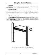
Page 25: ...o 250 VAC 20 to 60 VDC for DC supply Allow at least 10cm 4 inch clearance at the rear and front of the Fiber Multiplexer for signal lines and interface cables 3 3 Mechanical Assembly The Fiber Multiplexer is designed for rack mount installation and only requires 1U space 1 3 4 in a standard EIA 19 or 23 inch rack It is highly recommended that the unit be placed in a rack The Fiber Multiplexer may ...

Page 26: ...with DC power supply DC 48V 20 60VDC is connected to the terminal block observing the proper polarity In the AC DC model both IEC receptacle and DC terminal block are provided for dual power operation The Fiber Multiplexer should always be grounded through the protective earth lead of the power cable in AC installations or via the frame ground connection for DC installations Figure 3 2 Supply conn...

Page 27: ...optical interface two interface connector groups are provided for connection to either the primary optical transmit and receive pair or to the redundant optical transmit and receive pair if the optical interface card has the redundant optical option The front panel also provides the connections to the RS 232 Console Interface terminal mode and to the LAN network for SNMP control when the SNMP opti...

Page 28: ... From here the de multiplexed signals are sent to the individual 4 CHANNEL Card module channel installed in the rear of the unit see 3 5 2 for removal replacement procedures To remove either interface module loosen the captive thumb screws until the threads are disengaged from the chassis Gently pull the card straight forward by the captive screws using equal force to avoid binding The card is onl...

Page 29: ...ee small flathead screws Using a No 2 Philips screwdriver remove the two upper and one lower screw then pull the module straight out refer to the pictures below To install the 4 Channel Port module reverse the procedure taking care when seating the module to avoid connector damage Gently seat it do not force it Re install the three flathead screws and do not over tighten Then re install the approp...

Page 30: ...installed must both be removed 3 Follow the procedure in 3 5 2 and remove the Port No 2 4 Channel Port module 4 The top cover is held in place by seven screws Remove the two upper screws on each side of the unit 5 From the back of the unit remove the upper screws on the far left far right and center of the unit The center screw is hidden unless the No 2 Port module is removed 6 Use your finger to ...

Page 31: ...over is no longer needed 4 Place the ribbon cable on the feature card with the cable going away from the back of the card noting the polarity of the cable Place the red stripe to pin 1 on the feature card 5 Place the RJ 45 connector into the hole cut out first align the three holes in the PC board with the three stand offs Insert the three pan head screws that were supplied with the external clock...

Page 32: ... it must be removed 2 Follow the procedure in 3 5 3 to remove the top cover 3 The connector for the SNMP daughter card is just behind the front panel display connector Carefully seat the card ensuring no pins are bent The three holes in the PCB should line up with the three stand offs on the mainboard 4 Install the three pan head screws supplied Tighten firmly but do not over tighten Refer to the ...

Page 33: ...e The super user password is 1021 no quotes Pressing ESC from this menu will briefly display the unit s firmware version number Pressing either ARROW key at this point will give the option to administer the remote site as long as there is a valid optical link Pressing the ENTER key at this point will page the operator at the top of the 10 top level Menus of either the local or selected remote unit...

Page 34: ...back functions can be set for each of 4 channels Browse sub menu items with arrow keys and select with Enter Browse setting options with arrow keys and set option with Enter P O R T 2 E 1 7 5 C O N F I G Entering this menu allows configuration of the Port Card installed in the Port 2 slot For the E1 card the in service state Line Code and Loop back functions can be set for each of 4 channels Brows...

Page 35: ...aying the current internal performance the nearest internal performance resetting the nearest or All performance data D A T E T I M E D I S P L A Y Entering this menu allows displaying the current date and time as well as setting or resetting the real time clock s date and time L O G O U T S Y S T E M Pressing ENTER at this menu will logout of the menu system back to the Administrator display and ...

Page 36: ...f Auto Disable Loopback OFF LLB RLB RRLB Status Opti 1 Opti 2 BERT ON OFF Pattern SYNC LOSS ErrIns ENTER insert 1 bit error ErrBit count of single bit errors RxBit count of received bits ErRate bit error rate on fiber Clear ENTER clears the error bit counter Port X YY Channel A D Service ON OFF Line Code HDB3 B8Z3 AMI Loopback OFF LLB NELLB RLB RRLB ALARM REPORT Clear History Threshold Set CV 255 ...

Page 37: ...port communication with the Fiber Multiplexer are 19 2K baud 8 bits no parity 1 stop bit and no flow control In the HyperTerminal program terminal window click the properties icon and set the communication parameters as in the following graphics Click the Configure button in the properties window and set the port settings When set properly click OK Figure 4 2 HyperTerminal port settings for Fiber ...

Page 38: ... setup of all parameters through the use of a standard text based terminal or any terminal emulation program running on a Personal Computer Make the appropriate connections start the terminal application apply power to the Fiber Multiplexer then press ENTER on the PC keyboard If you are using HyperTerminal the display should similar to the following the version may be different 4 3 Terminal Connec...

Page 39: ... Define System Parameters Note that the upper left corner will display the word LOCAL in inverse text indicating that the Terminal Mode connection is to the local unit and not the remote unit If this is our first time connecting and we wish to configure or check the unit s configuration we can directly enter the Define System Parameter menu by pressing 2 The following menu will be displayed LOCAL ...

Page 40: ...ering 3 The item 4 Load User Setting will immediately load a previously saved user setting The item 5 Modify Password the password to enter administration of this unit may be modified The password setting must be 4 numerals When logging in the password prompt is an empty blank line Enter the 4 digit password and press Enter To clear the administration password modify it by entering four zeros 0000...

Page 41: ...ical 1 Optical 1 Work 2 Optical 2 Standby 3 ALS Auto 4 Loopback OFF Please select the item or ESC to previous menu The functions in this menu allow configuration of the Optical Card as follows Optical 1 set to working mode or Off Optical 2 set to Standby mode or Disabled ALS Auto Laser Shutoff set to Auto or Disabled Loopback set to Off or to Local loopback 4 5 6 Port Option Configuration If we ES...

Page 42: ... Loopback status for the selected channel press 3 LOCAL Define Port 1 Parameter Ch A Ch B Ch C Ch D 1 Service ON ON ON ON 2 Line Code HDB3 HDB3 HDB3 HDB3 3 Loopback OFF OFF OFF OFF Loopback 1 OFF 2 LLB Local Loopback 3 NELLB Near End Local Loopback 4 RLB Remote Loopback 5 RRLB Request Remote Loopback Please select the item or ESC to previous menu Choose the desired loopback mode from the menu show...

Page 43: ...ividual channel with the corresponding letter A B C D or press ESC to exit this menu For an example of turning service off for Channel D press D LOCAL Define Port 2 Parameter Ch A Ch B Ch C Ch D 1 Service ON ON ON ON 2 Line Code B8ZS B8ZS B8ZS B8ZS 3 Loopback OFF OFF OFF OFF Please select Function 1 3 or ESC to previous menu Notice that ch A is highlighted indicating it is the selected channel To ...

Page 44: ...nnel settings select the individual channel with the corresponding letter A B C D or press ESC to exit this menu For an example of setting the timing mode for Channel A press A The following menu is displayed LOCAL Define Port 3 Parameter Ch A Ch B Ch C Ch D 1 Service ON ON ON ON 2 Rate Kbps 2048 2048 2048 2048 3 Timing Trans Trans Trans Trans 4 Loopback OFF OFF OFF OFF 5 CTS ON ON ON ON Please se...

Page 45: ...er to the bridge card section for setting the DIP switch located physically on the bridge card module 4 5 7 Alarm Threshold Settings Next we will escape back to the Define System menu and select item 7 for the Alarm Threshold settings Press 7 and the display will look like this LOCAL Define Alarm Threshold 1 CV Code Violation 255 2 ES Error Seconds 300 Sec 3 SES Severely Error Seconds 300 Sec 4 UA...

Page 46: ...then press 8 for item 8 LOCAL Date and Time 1 Date 2003 10 01 2 Time 03 34 15 Please select the item or ESC to previous menu To correct the date and time press 1 for the date or 2 for the time The cursor will be placed on the setting for year in Date or for hour in Time LOCAL Date and Time 1 Date 2004 03 03 2 Time 14 15 15 Press Key to set or Press ESC to Exit Use the and keys to the correct Date ...

Page 47: ...at all Port cards are installed and that all 4 channels 1A 1B are in service v without any errors from local or remote side except for Port 4 which is a LAN card The LAN card combines the entire port throughput into a single WAN bridge The optical 1 O1 connection is working W and optical 2 O2 is in standby S mode Both power supplies P1 and P2 are active in both local and remote side units The disp...

Page 48: ... Reset Current Interval The performance data for all 16 channels is shown 4 for each of 4 ports plus the optical performance There is a total of 96 history pages 00 95 with 00 being the current performance display Each performance history represents a 15 minute interval 900 seconds while all 96 history intervals represent the last 24 hours To view a previous performance history interval press the ...

Page 49: ...Loop Backs for the Optical interface and the secondary Optical interface if redundant as well as Local Loop Back Near End Loop Back Remote Loop Back and Request Remote Loop Back for the E1 T1 and Data communication 4 Channel Port Cards 5 2 Loop Back Modes 5 2 1 Optical Loop Back LLB Optical local loop back near end NE far end FE RLB Optical Remote loop back near end NE far end FE RRLB Request opti...

Page 50: ...5 2 2 E1 T1 4 Channel Port Card Loop Back LLB T1 E1 local loop back near end NE far end FE NELLB near end local loop back near end NE far end FE RLB T1 E1 remote loop back near end NE far end FE RRLB request T1 E1 remote loop back near end NE far end FE ...

Page 51: ...cal loop back near end NE far end FE RLB remote loop back near end NE far end FE V54up V 54 remote loop back near end NE far end FE V54dn will release the remote loop back Set the clock Rate on all units in any configuration to equal the actual transmission rate Without proper setting the loop back functions will not operate properly ...

Page 52: ... DTE TC TC RC RC FMUX is placed between existing DCE and DTE External Timing DCE DTE DCE DTE ETC TC RC FMUX is placed between two DCE devices Transparent Timing DCE DTE DTE DCE ETC TC RC TC RC ETC Int Osc Rate n x 64 where n 1 to 32 Recover from optical Rate n x 64 Ext Clk Rate n x 64 where n 1 to 32 Recover from optical Rate n x 64 Trans Rate n x 64 where n 1 to 32 Trans Rate n x 64 where n 1 to ...

Page 53: ...ling protocol and operates at the OSI Layer 7 Layer 7 is the Application Layer Other IP applications that operate at this layer are FTP Telnet HTTP SMTP etc All management traffic is initiated by the SNMP based network management station Only the addressed managed entity agent answers the polling of the management station except for trap messages 6 2 SNMP Operations The SNMP protocol includes four...

Page 54: ...d tree like structure root over leaves with each definition of a managed instance forming one leaf located at the end of a branch of that tree Each leaf in the MIB is reached by a unique path therefore by numbering the branching points starting with the top each leaf can be uniquely defined by a sequence of numbers The formal description of the managed objects and the MIB structure is provided in ...

Page 55: ... to communicate with it and the access rights associated with each community this is the SNMP community name table of the entity In general SNMP agents support two types of access rights Read only the SNMP agent accepts and processes only SNMP getRequest and getNextRequest commands from management stations which have a read only community name Read write the SNMP agent accepts and processes all th...

Page 56: ...ff Please select the item number Note that the upper left corner will display the word LOCAL in inverse text indicating that the Terminal Mode connection is to the local unit and not the remote unit If this is our first time connecting and we wish to configure or check the unit s configuration we can directly enter the Define System Parameter menu by pressing 2 The following menu will be displayed...

Page 57: ...net mask for the network that the card is attached to Item number 3 is the default gateway for the network that the card is attached to and is required if the Fiber Multiplexer is to be managed from a different subnet Item number 4 is the IP address of a server running the TFTP protocol trivial FTP used for updating the SNMP firmware image in the SNMP card Item number 5 is the path and filename of...

Page 58: ...ead write secret in this case and read only public access and assigning a community string to an access IP an administrator can control access to the Fiber Multiplexer Note that in the above example the management workstation with IP address 172 24 1 126 and using the community string secret has full read and write access and receives traps The management station at 192 168 0 15 has read only priv...

Page 59: ...Values Note local_system local_System External Clock External clock clock_Off 0 clock_E1 PCM 1 clock_E1 TTL 2 clock_T1 PCM 3 clock_T1 TTL 4 clock_X TAL 5 error_Nocard 254 Cannot be set unless external clock option installed local_Alarm Relay Alarm relay relay Both 0 relay Audible 1 relay Visible 2 relay All_Off 3 local_Active Save load user setting active None 0 active Save_User_Setting 1 active L...

Page 60: ... A setting service service_On 0 service_Off 1 error_LanCard 252 error_WrongType 253 error_Nocard 254 same for Ch A D E1 T1 local_p1cha_e1t1_Line Code E1 T1 channel A setting line code line code_HDB3 B8ZS 0 line code_AMI 1 error_LanCard 252 error_WrongType 253 error_Nocard 254 same for Ch A D E1 T1 local_p1cha_e1t1_Loopba ck E1 T1 channel A setting loop back loopback_Off 0 loopback_LLB 1 loopback_N...

Page 61: ...ta rate_1280 20 data rate_1344 21 data rate_1408 22 data rate_1472 23 data rate_1536 24 data rate_1600 25 data rate_1664 26 data rate_1728 27 data rate_1792 28 data rate_1856 29 data rate_1920 30 data rate_1984 31 error_LanCard 252 error_WrongType 253 error_Nocard 254 local_p1cha_data comm_Timing Data channel A setting timing timing_Trans 0 timing_Recovery 1 timing_Ext CLK 2 timing_Int OSC 3 error...

Page 62: ... local_Performance local_performance_Optical optical performance Line CV 0 ES 0 Path CV 0 ES 0 SES 0 UAS 0 Read Only local_performance_P1 ChA channel performance Line CV 0 ES 0 Path CV 0 ES 0 SES 0 UAS 0 Read Only continue P1 4 ChA D local_performance_index history index Integer 0 95 local_performance_history_ optical optical history Line CV 0 ES 0 Path CV 0 ES 0 SES 0 UAS 0 Read Only local_perfor...

Page 63: ..._LanCard 252 error_WrongType 253 error_Nocard 254 local_SES SES alarm threshold ses_300s 0 ses_600s 1 ses_900s 2 error_LanCard 252 error_WrongType 253 error_Nocard 254 local_UAS UAS alarm threshold uas_300s 0 uas_600s 1 uas_900s 2 error_LanCard 252 error_WrongType 253 error_Nocard 254 end of local branch remote_System identical to local branch ...

Page 64: ... Loss OFF Ext Clock Signal Loss ON Ext Clock Signal Loss OFF Port 1 Ch A E1 T1 BPV Error Port 1 Ch B E1 T1 BPV Error Port 1 Ch C E1 T1 BPV Error Port 1 Ch D E1 T1 BPV Error Port 2 Ch A E1 T1 BPV Error Port 2 Ch B E1 T1 BPV Error Port 2 Ch C E1 T1 BPV Error Port 2 Ch D E1 T1 BPV Error Port 3 Ch A E1 T1 BPV Error Port 3 Ch B E1 T1 BPV Error Port 3 Ch C E1 T1 BPV Error Port 3 Ch D E1 T1 BPV Error Por...

Page 65: ......

Page 66: ......

Page 67: ......

Page 68: ......

Page 69: ... AMI HDB3 B8Z3 AMI HDB3 B8Z3 AMI HDB3 B8Z3 AMI HDB3 B8Z3 Loop Back Off LLB NELLB RLB RRLB PORT Card 2 G 703 E1 T1 DS1 Datacomm Bridge Channel A Channel B Channel C Channel D Service ON OFF Service ON OFF Service ON OFF Service ON OFF Line Code Line Code Line Code Line Code AMI HDB3 B8Z3 AMI HDB3 B8Z3 AMI HDB3 B8Z3 AMI HDB3 B8Z3 Loop Back Off LLB NELLB RLB RRLB PORT Card 3 G 703 E1 T1 DS1 Datacomm ...

Page 70: ......

Page 71: ......

Page 72: ...Converter Series CTC Union Technologies Co Ltd Far Eastern Vienna Technology Center Neihu Technology Park 8F No 60 Zhouzi Street Neihu Taipei Taiwan Phone 886 2 2659 1021 Fax 886 2 2799 1355 E mail info ctcu com http www ctcu com ...

Reviews: