background image

148 •  AL-SERIES

3

Electronic Self-Leveling

Rotary Laser

A

B

C

D

E

G

F

H

I

J

K

ICONES

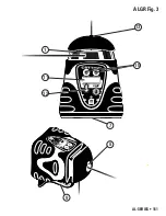
CARACTERÍSTICAS - Fig. 1, 2 & 3

1. Laser Rotativo Auto nivelável (+/-5º) – (Duplo Raio só ALHV,

ALHV-G e ALGR)

2. Indicador da carga das baterias   

Quando TODAS as luzes estão acesas, a carga está

completa. Quando o indicador está com as luzes Amarelas

é altura de substituir/carregar as baterias

(só ALH, ALHV, e ALHV-G)

3. Indicador do Sistema de Segurança de Altura (Anti Drift

System) - (só ALH, ALHV, e ALHV-G)

4. Interruptor ON/OFF    
5. Indicador Modo manual (só ALH, ALHV-G, e ALHV-G)
6. Teclas de Ajuste Manual da Rampa(só ALH)
7. Adaptação a tripé com rosca de 5/8 - 11 (para trabalho 

de nível)

8. Ponto de mira (alinhamento) dos eixos “X“ e “Y“
9. Asa Robusta (Suporte para Alinhamentos e Trabalhos

Verticais com adaptação 5/8 -11 só ALHV, ALHV-G, e ALGR)

10. Teclas de Selecção/Ajustamento (só ALGR)
11. Mostrador Digital LCD (só ALGR)
12. Tecla para Selecção de Modo (só ALGR )

Summary of Contents for ALGR

Page 1: ...ser Instruction Manual Manual de Instrucciones Manuel d Instructions Manuale di Istruzioni Bedienungsanleitung Instru es de Utiliza o Electronic Self Leveling Rotary Laser models ALH ALHV ALHV G ALGR...

Page 2: ...2 AL SERIES LD440 3 3...

Page 3: ...HV Fig 6 A L G R M OD E SE LE CT SE LE CT VERTICAL LINE PLUMB BEAM Fig 7 Y A x i s Y MORE X MORE LESS LESS ALGR MODE SELECT SELECT X AXIS ERROR Y AXIS ERROR SPINDLE ERROR AL Series Errors Fig 8 Fig 9...

Page 4: ...ssible only when the operating and safety information are read completely and the instructions contained therein are strictly followed The use of controls adjustments or the performance of procedures...

Page 5: ...T use any optical instruments such as but not limited to telescopes or transits to view the laser beam Serious eye injury could result ALWAYS remove the batteries when cleaning the laser light apertur...

Page 6: ...terior Exterior 10 10 FEATURES Low Battery Indicator Anti Drift System Single Slope Grade Dual Slope Grade Cross Axis Leveling Dual Beam Scanning Angle Feature Directional Head Positioning Variable Sp...

Page 7: ...icator ALH ALHV ALHV G only 4 Power ON OFF LED Indicator 5 Manual Mode LED Indicator ALH ALHV ALHV G only 6 Manual Grade Adjustment Buttons ALH ALHV ALHV G 7 5 8 11 Tripod Mounting Threads for level w...

Page 8: ...8 AL SERIES 1 5 4 8 9 7 3 2 6 ALH Fig 1...

Page 9: ...AL SERIES 9 ALHV ALHV G Fig 2 8 9 7 ALHV A L H V 1 3 4 2 13 6...

Page 10: ...10 AL SERIES ALGR Fig 3 8 9 7 ALGR MODE SELECT SELECT 1 11 10 12 A L G R M O D E S E L E C T S E L E C T 13...

Page 11: ...e benchmark to ensure that your setup has not moved APPLICATIONS Benchmark Professional grade Accuracy and Durabillity for general construction and site preparation jobs Including Grading and excavati...

Page 12: ...he laser to the optional wall mount bracket Be sure the control buttons are facing outward Tightening the locking screw will secure the instrument to the bracket 2 After installing the first piece of...

Page 13: ...to rotate before leveling is complete The self leveling speed is approximately 1 per 4 seconds 3 After self leveling the instrument will begin operating in Rotation Mode NOTE The ALHV ALHV G will ret...

Page 14: ...peed is 100 RPM and the highest is 1000 RPM Sweep or Scanning Mode Models ALHV ALHV G and ALGR Instead of creating a room wide reference line the Sweep Scanning Mode creates a shorter brighter laser c...

Page 15: ...n until the instrument is in Spot Mode Press the F or G to rotate the laser head clockwise or counter clockwise Pressing and holding the G or F button moves the rotating beam more quickly model ALGR U...

Page 16: ...evel If Auto Level Mode is set to OFF the instrument will NOT re level if the instrument is moved out of level and will continue to operate use this option when using an adapter or mount that allows y...

Page 17: ...r selectable When the instrument is OFF press and hold the right SELECT button and then press the ON OFF A button Once the instrument is on turn the instrument off for 15 sec and then back on This wil...

Page 18: ...choose either the X axis or Y axis An on the display will indicate the selected axis Press the left SELECT button to increase slope press the right SELECT button to decrease slope Ideally for single a...

Page 19: ...oving the entire instrument useful for floor and wall tile installation walls or partitions etc The laser will now remain aligned to your target even if you enter other modes Rotation Spot Point to Po...

Page 20: ...d can cause injury or fire To reduce this risk ALWAYS follow all instructions and warnings on the battery label and package DO NOT short any battery terminals DO NOT charge alkaline batteries DO NOT m...

Page 21: ...an the specified accuracy Repeat the above steps to ensure a correct reading If the distance is greater than specified accuracy you will need to calibrate the X axis NOTE For ALHV ALHV G and ALGR Spot...

Page 22: ...he instrument while holding the MODE button down 2 Release both buttons at the same time and wait for calibration instructions to appear on screen You will have to select the direction of calibration...

Page 23: ...ervice center for assistance Laydown Position Peg Test Z axis ALHV ALHV G ALGR only 1 To test the Z axis place the instrument on its back using the built in trivet control panel facing upward 100 feet...

Page 24: ...use Use a soft dry cloth to remove any dirt or moisture from the instrument Do not use benzene paint thinner or other solvents to clean the instrument Store the instrument in its case when not in use...

Page 25: ...nning Feature Warranty Operating Temperature 650 nm 5mW Red Visible Laser Green Visible Laser 532 nm 635 nm 10mW 1 16 in 1 6mm 1 8 in 3mm N A No Yes Single Slope cross axis Dual Slope cross axis Dual...

Page 26: ...h alkaline batteries when available WARRANTY Three Year Warranty CST berger warrants this electronic measuring tool against deficiencies in material and workmanship for a period of three years from th...

Page 27: ...ssing the ON OFF pad The LCD symbols will momentarily flash and the coarse beam indicator symbol will remain lit and the audio signal will be on Fig 21 2 Expose the beam capture window of the laser de...

Page 28: ...beep to acknowledge frequency and volume setting as above The LCD display of the detector LD 440 has seven distinct channels of information indicating the position of the detector in the plane of las...

Page 29: ...nd calibration features with a range of up to 100 feet 30m Requires 2 AA Alkaline batteries NOTE When using the remote in Line Position Mode the LEFT and RIGHT buttons can be used to position the refe...

Page 30: ...crement increment the Y axis grade respectively The 6 Long and 7 Short buttons activates the sweep function The Long button elongates the sweep and the Short button shortens it The CCW and CW buttons...

Page 31: ...GURIDAD Y ESPECIFICACIONES Es posible trabajar con el aparato sin peligro s lo despu s de haber le do atentamente las instrucciones para el uso y las advertencias de seguridad y siguiendo estrictament...

Page 32: ...telescopios o teodolitos para ver el E haz de l ser Podr dar como resultado heridas serias en los ojos SIEMPRE retire las bater as cuando limpie la abertura del haz l ser o el lente l ser NO OPERE la...

Page 33: ...o ADS Inclinaci n simple individual Doble inclinaci n simult nea Autonivelaci n del eje transversal Cabeza con plomada a techo Modo barrido 4 ngulos de apertura Rotaci n de la cabeza a ambos lados B s...

Page 34: ...ALHV 3 Indicaci n alarma antimovimiento ADS s lo ALH ALHV 4 Interruptor ON OFF conexi n desconexi n 5 Indicaci n Funci n Manual s lo ALH ALHV 6 Interruptores ajuste inclinaci n manual s lo ALH 7 Tapa...

Page 35: ...AL SERIES 35 1 5 4 8 9 7 3 2 6 ALH Fig 1...

Page 36: ...36 AL SERIES ALHV ALHV G Fig 2 8 9 7 ALHV A L H V 1 3 4 2 13 6...

Page 37: ...AL SERIES 37 ALGR Fig 3 8 9 7 ALGR MODE SELECT SELECT 1 11 10 12 A L G R M O D E S E L E C T S E L E C T 13...

Page 38: ...nfiguraci n no ha variado APLICACIONES Establecer una referencia Precisi n y durabilidad profesional para la construcci n en general y preparaci n de los diversos trabajos Nivelaciones y excavaciones...

Page 39: ...ara el manejo del receptor que aparecen en este manual Uso en falsos techos con rejilla 1 Monte el l ser en el soporte de pared opcional Aseg rese de que los botones de control queden mirando hacia af...

Page 40: ...ciones Nivelaci n 1 El l ser se puede colocar sobre cualquier superficie lisa o montarlo en un tr pode est ndar con rosca de 5 8 11 2 Presionar el interruptor A una vez el bot n POWER en el ALGR y dej...

Page 41: ...7 2 Presionar el interruptor A una vez el bot n POWER en el ALGR y dejar aprox 60 segundos al l ser para que se ponga a nivel NOTA Para un ajuste fino de la l nea vertical o de la plomada ver Modo Po...

Page 42: ...echa o izquierda Pulsar el bot n MODE para empezar el barrido entre los dos puntos Se puede usar los botones SELECT para reajustar la posici n de cada punto si es necesario NOTA En modo barrido o punt...

Page 43: ...atenci n al cliente de CST berger Error Spindle Motor Modelos ALH ALHV y ALHV G Si con el motor en funcionamiento la cabeza no gira se produce un error de Spindle indicado mediante el encendido inter...

Page 44: ...a unidad se mueve fuera de nivel Encender el modo ADS seleccion ndolo en el modo de autonivelado y usando el bot n MODE para volver al modo deseado Cuando se activa la funci n ADS hay que esperar 1 mi...

Page 45: ...en el eje X pulsando los botones n 2 3 del mando a distancia RC700 Ajuste de las Inclinaciones Inclinaci n manual doble Modelo ALGR Esta funci n permite trabajos m s especializados como preparaci n de...

Page 46: ...ocurre un movimiento s lo sobre el eje que est inclinado la funci n ADS podr a no detectarlo Modo posici n l nea Modelos ALHV ALHV G ALGR En este modo la unidad permite ajustar la posici n de la l nea...

Page 47: ...si la bater a est baja s lo el LED rojo est encendido En el modelo ALGR si la bater a est baja la pantalla indicar BATERIA BAJA Si el l ser funciona de una manera err nea cambie las pilas Fig 15 1 Qu...

Page 48: ...sde ese momento en adelante Permita al l ser aprox 60 segundos para que se nivele antes de controlarlo Comprobaci n de error en la rotaci n horizontal Eje X Todos los modelos 1 Coloque la unidad a 100...

Page 49: ...ay que subir el rayo presionando el bot n arriba 4 Las correcciones se guardan autom ticamente Comprobar de nuevo la precisi n de la rotaci n repitiendo los pasos 1 4 de la secci n precedente La compr...

Page 50: ...rror en la rotaci n horizontal y calibraci n Eje Y Todos los modelos Si desea comprobar tambi n el eje Y montar la unidad en un tr pode y situarlo aprox a 100 pies 30 metros de distancia del objetivo...

Page 51: ...s dos botones al mismo tiempo y esperar hasta que las instrucciones de calibraci n aparezcan en pantalla Usar el bot n SELECT derecho siguiendo el cuadro que se encuentra en el cap tulo Calibraci n de...

Page 52: ...e aprox 25 horas aprox 15 horas aprox 30 horas de uso intermitente Diodo L ser Rayo L ser Precisi n a 30 m Inclinaci n Distancia con el receptor l ser Autonivelaci n Alimentaci n Dimensiones Funci n d...

Page 53: ...tamente Como en la mayor a de pack de pilas de n kel cadmio cuanto m s cargado est m s le costar cargarse completamente El pack bater a debidamente cargado durar aprox 14 horas El pack de pilas tendr...

Page 54: ...nsable del correcto uso y mantenimiento del instrumento Y adem s es de su responsabilidad controlar la buena ejecuci n del trabajo y por consiguiente la calibraci n del instrumento Mantenimiento y cal...

Page 55: ...har Mover el receptor hacia abajo cuando el indicador de se al superior est encendido una pulsaci n de tono corto de audio se escuchar Cuando la se al est nivelada la l nea indicadora de nivel se ence...

Page 56: ...a pantalla de nivel LED es til para detectar la posici n del l ser a distancia similar a la pantalla LCD o en condiciones de poca iluminaci n El indicador LED inferior muestra que el detector est dema...

Page 57: ...Manual Posiciona el instrumento en grado manual si ADS no es seleccionado En posici n vertical permite ajuste manual del laser 10 Sleep posiciona el instrumento en modo dormir al apagar todas las func...

Page 58: ...de haber soltado el bot n Mode Usar los botones CCW y CW para fijar el primer punto despu s soltar el bot n PtoP Usar otra vez los botones CCW y CW para fijar el segundo punto y luego soltar el bot n...

Page 59: ...avant l autorisation crite de CST berger SURET ET CERTIFICATIONS Avant d utiliser l appareil et pour ne courir aucun risque lisez attentivement la notice et les consignes de s curit qui y sont imparti...

Page 60: ...u th odolite pour voir le faisceau laser De graves blessures oculaires pourraient en r sulter Enlevez TOUJOURS les piles quand vous nettoyez l ouverture de lumi re laser ou le verre du laser N UTILISE...

Page 61: ...de charge de batterie Syst me Tilt Simple pente Double pente Fonction Angles de scanning Double faisceau Fonction scanning Contr le de rotation point par point Positionnement automatique du point d qu...

Page 62: ...recharger ALH ALHV ALHV G uniquement 3 T moin ADS ALH ALHV ALHV G uniquement 4 Bouton Marche Arret 5 T moin Manuel ALH ALHV ALHV G uniquement 6 Boutons pour le r glage manuel de la pente ALH uniquemen...

Page 63: ...AL SERIES 63 1 5 4 8 9 7 3 2 6 ALH Fig 1...

Page 64: ...64 AL SERIES ALHV ALHV G Fig 2 8 9 7 ALHV A L H V 1 3 4 2 13 6...

Page 65: ...AL SERIES 65 ALGR Fig 3 8 9 7 ALGR MODE SELECT SELECT 1 11 10 12 A L G R M O D E S E L E C T S E L E C T 13...

Page 66: ...t votre point de r f rence afin de vous assurer qu il n a pas t d plac APPLICATIONS Point de r f rence Pr cision de pente et robustesse professionnelles niveau laser id al pour tous travaux dans le BT...

Page 67: ...gurant dans le pr sent manuel Utilisations pour grilles de plafond 1 Fixez l instrument au support de fixation murale fourni en option Assurez vous que les boutons de commande sont acc ssibles Serrez...

Page 68: ...tial Mise niveau 1 Installez le laser sur un tr pied ou support avec filetage standard 5 8 11 2 Une fois le laser install appuyez sur le bouton Marche Arr t A afin de le mettre en route Laissez le las...

Page 69: ...enter la visibilit du plan engendr par la rotation de la t te on peut ainsi travailler aussi bien l horizontale qu la verticale Mod le ALHV ALHV G Lorsque vous appuyez sur le bouton E vous pouvez r gl...

Page 70: ...uche MODE D placez le point droite ou gauche comme pour le point A Appuyez nouveau sur la touche MODE la t te oscille entre les points s lectionn s Remarque En mode Ligne et en mode Scan Point point l...

Page 71: ...ur le mettre niveau puis mettez le nouveau sous tension Si l appareil continue de faire des erreurs contactez le service client CST berger Erreur fuseau Disfoncionnement de l axe rotatif Spindle Motor...

Page 72: ...evez ou abaissez la colonne centrale du tr pied pour r gler de nouveau la hauteur initiale de rotation Vous disposez d une minute pour cette op ration de contr le avant que l ADS ne redevienne actif P...

Page 73: ...NCLINAISON ou MOINS D INCLINAISON Laissez largement le temps l instrument de s adapter aux modifications ou r glages effectu s Fig 10 Mode Manuel Mod le ALH ALHV ALHV G et ALGR Le mode Manuel d sactiv...

Page 74: ...deux axes Pour quitter le Mode Pentes appuyer sur la touche Mode pendant 4 5 secondes vous repassez au Menu de s lection il n est pas n cessaire d appuyer sur la touche Mode pendant 4 5 secondes pour...

Page 75: ...extr mement rapide sans devoir d placer physiquement le laser Une fois que le plan de la lumi re verticale a t align avec votre point de r f rence le laser reste align galement lorsque vous lancez les...

Page 76: ...les Remplacez les quatre piles en m me temps 3 Replacez les piles en v rifiant que le compartiment est bien positionn Remarque Ne m langez jamais anciennes et nouvelles piles Remplacez toutes les pile...

Page 77: ...ompl tement ce processus peut prendre jusqu 60 secondes Test du positionnement vertical de l axe X Tous les mod les 1 Pour tester le positionnement de l axe X fixez le laser sur un tr pied ou placez l...

Page 78: ...incr mentez n gativement la position du laser par rapport l axe X 4 Les corrections sont sauvegard es automatiquement Vous devez ensuite r p ter le test de positionnement de l axe X points 1 4 afin de...

Page 79: ...e contraire si B se trouve en dessous de A 4 Appuyez sur MODE pour quitter le mode Calibrage et enregistrez les corrections en teignant l instrument Il est conseill de refaire la proc dure de contr le...

Page 80: ...e hors tension Mod le ALHV ALHV G 1 Remettez le sous tension tout en maintenant le bouton G enfonc Alors rel cher le bouton A Le mode talonnage est activ lorsque les voyants PILE et ADS clignotent en...

Page 81: ...ariable tr mn 0 1000 Variable tr mn 600 tr mn LR20 NI MH 60 heurs en usage intermittent 25 Hrs 15 Hrs 30 heurs en usage intermittent Diode laser Couleur laser Pr cision horisontal 30 m 100 pi Pentes M...

Page 82: ...le positionnement du bo tier des piles et v rifiez s il est bien viss sa base Contr lez aussi les contacts car il arrive que des piles vendues dans le commerce aient des dimensions l g rement diff re...

Page 83: ...tion de ce produit ou r sultant d un cas de force majeur L usure normale de ce produit ou de ses composants cons quence de l utilisation normale de ce produit sur un chantier n est pas couverte dans l...

Page 84: ...d tecteur sur une mire le cas ch ant Allumez le d tecteur en appuyant sur le bouton MARCHE ARR T de l instrument Les symboles sur la fen tre d affichage clignotent pendant un instant le voyant du fai...

Page 85: ...t faible il y a un bip court suivi d un bip plus long Quand le volume est fort il y a un bip court suivi d un bip fort et plus long La fr quence sonore peut tre s lectionn e entre 4 sons diff rents Po...

Page 86: ...le mod le ALHV ALHV G uniquement La t l commande 57 RC700 contr le toutes les fonctions de la nivelle l exception de la mise sous tension de l ADS et du r glage La t l commande peut tre utilis e une...

Page 87: ...tion de base est de 600 tours min Quand le mode pente est activ les boutons DOWN bas ou UP haut permettront de r duire ou accentuer respectivement l inclinaison de l axe Y Appuyer d abord sur la touch...

Page 88: ...durre questo manuale senza previo consenso scritto della CST berger SICUREZZA E CERTIFICAZIONI E possibile lavorare con lo strumento senza incorrere in pericoli soltanto dopo aver letto attentamente l...

Page 89: ...telescopi tacheometri ecc per vedere il raggio laser Ne pu derivare una grave lesione agli occhi Rimuovere SEMPRE le batterie quando si esegue la pulizia della finestra di uscita del raggio o delle l...

Page 90: ...o di carica della batteria Allarme di Spostamento Singola pendenza Doppia pendenza Livellamento dell asse trasversale Doppio raggio Scansione Posizionamento del raggio fisso Centramento automatico del...

Page 91: ...icare 3 LED ADS solo ALH ALHV e ALHV G 4 Pulsante di Accensione e Spegnimento 5 LED modo manuale solo ALH ALHV e ALHV G 6 Pulsanti impostazione pendenza manuale solo ALH 7 Base filettata standard 5 8...

Page 92: ...92 AL SERIES 1 5 4 8 9 7 3 2 6 ALH Fig 1...

Page 93: ...AL SERIES 93 ALHV ALHV G Fig 2 8 9 7 ALHV A L H V 1 3 4 2 13 6...

Page 94: ...94 AL SERIES ALGR Fig 3 8 9 7 ALGR MODE SELECT SELECT 1 11 10 12 A L G R M O D E S E L E C T S E L E C T 13...

Page 95: ...ti accidentali controllando il posizionamento del laser in base al punto di riferimento APPLICAZIONI Riferimenti Grado di precisione professionale e affidabilit per le costruzioni generali e la prepar...

Page 96: ...atevi che i pulsanti di controllo dello strumento siano accessibili 2 Dopo aver installato il primo tratto del profilo perimetrale del controsoffitto all altezza voluta fissate saldamente la staffa o...

Page 97: ...na volta il pulsante A POWER nel modello ALGR ed aspettate che lo strumento sia livellato Il tempo massimo di livellamento di 60 secondi NOTA la testa pu iniziare a girare prima che il livellamento si...

Page 98: ...te il paragrafo relativo all Allineamento Modo rotazione Modelli ALHV ALHV G e ALGR Col modo rotazione possibile regolare la velocit di rotazione della testa Questa caratteristica consente di incremen...

Page 99: ...r fissare il punto finale B premete di nuovo il tasto MODE Spostate il punto a destra DSTRA o a sinistra SNSTRA Premete di nuovo il tasto MODE la testa oscilla tra i punti selezionati Nota Nel modo Sc...

Page 100: ...Error Modelli ALH ALHV e ALHV G Se la testa del laser non ruota oppure ruota ma non alla velocit impostata lo strumento dar un indicazione di errore Fig 8 Fate riferimento alla sezione Soluzione dei...

Page 101: ...to alzate o abbassate la colonna centrale del treppiedi per impostare di nuovo l altezza iniziale di rotazione Avete un minuto di tempo per l operazione di controllo prima che l ADS sia nuovamente att...

Page 102: ...PIU o MENO a seconda delle necessit dello scavo lasciate tempo al laser perch raggiunga la pendenza Fig 10 Modo manuale Tutti i modelli Nel modo MANUALE disattivato il controllo elettronico della mes...

Page 103: ...si ottiene SOLO se la testa del treppiedi perfettamente livellata In caso contrario la pendenza massima impostabile dipende dall inclinazione della testa del treppiedi pi fuori bolla minore la penden...

Page 104: ...il laser si trova in posizione verticale Il piano rotante a squadro con la linea laser determinata dal punto fisso che esce in orizzontale dalla testa del livello NOTA I tasti destro e sinistro 2 e 3...

Page 105: ...rie conformemente alle disposizioni locali NON gettare le batterie nel fuoco TENERE le batterie fuori della portata dei bambini RIMUOVERE le batterie se non si usa l apparecchio per diversi mesi Batte...

Page 106: ...ig 16 Non muovete il laser dalla sua posizione attuale e spegnetelo Modello ALH 1 Accendete il laser tenendo premuto contemporaneamente il tasto B quindi rilasciate il tasto A Il laser si trova ora in...

Page 107: ...omento e aspettate finch non appaiono sul display le istruzioni per la calibrazione Dovrete selezionare l asse su cui dare le correzioni per la calibrazione 3 Usate il pulsante SELECT di destra e segu...

Page 108: ...pavimento o su una superficie abbastanza piana ad una distanza di circa 30 m dalla base di una parete in modo che la tastiera di controllo sia rivolta verso l alto e un lato dello strumento verso la...

Page 109: ...rimento 4 Premete il pulsante MODE per uscire dal Modo Calibrazione dell Asse Z e salvate le variazioni apportate spegnendo il laser FINE Si consiglia di ripetere la procedura di controllo descritta a...

Page 110: ...livellamento Alimentazione Dimensioni Scansione Garanzia Temperatura di lavoro 650 nm 5mW Raggio rosso visibile Raggio verde visibile 532 nm 635 nm 10mW 1 6mm 3mm N A No si singola cross axis doppia c...

Page 111: ...ottimali dopo cinque cicli di carica scarica Il laser non si autolivella e o la testa non ruota oppure indica un Errore di Rotazione Assicuratevi che il laser si trovi all interno del suo campo di aut...

Page 112: ...e 13 Freccia verso l alto 6 Volume ON OFF 14 Volume sonoro 7 Display LCD posteriore 15 Precisione della banda 8 Comparto batteria 16 A livello 9 Magneti industriali scarica 17 Batteria scarica Aliment...

Page 113: ...e acustico Spento Alto 105 dBa Molto Alto 125 dBa Controllo del Volume Audio La pressione del pulsante del volume Fig 20 6 attiva un funzionamento ciclico volume spento volume basso volume alto Dopo o...

Page 114: ...olla tutte le funzioni del laser ad eccezione dell accensione dell ADS e della calibrazione Il telecomando pu essere utilizzato fino ad una distanza massima di 30 m dal laser Per un funzionamento migl...

Page 115: ...ostata La velocit di rotazione all accensione 600 giri min I tasti 4 e 5 ora aumenteranno o diminuiranno la velocit di rotazione In Modo Pendenza i tasti 4 e 5 aumenteranno e diminuiranno la pendenza...

Page 116: ...eistiges Eigentum von CST berger und d rfen ohne Zustimmung von CST berger weder verwendet noch ver ndert werden Dieses Dokument darf ohne schriftliche Zustimmung von CST berger weder kopiert noch and...

Page 117: ...and absichtlich oder versehentlich in den Laserstrahl blicken k nnte Dies kann zu schweren Augenverletzung en f hren Benutzen Sie KEINE optischen Instrumente u a Teleskope oder Theodolite um den Laser...

Page 118: ...nzeige Lichtanzeige beim Anti Drift System Einfache Neigung Zweifache Neigung Querachsnivellierung Lotstrahl Scanning Funktion Positionierung des Rotationskopfes Automatische Positionierung des Lotstr...

Page 119: ...ALHV ALHV G 3 LED berwachungsfunktion ADS nur ALH ALHV ALHV G 4 EIN AUS Schalter 5 LED Nivellieren Aus nur ALH ALHV ALHV G 6 Manuelle Neigungseinstellung nur ALH 7 Batteriefach 5 8 11 Gewinde f r Stat...

Page 120: ...120 AL SERIES 1 5 4 8 9 7 3 2 6 ALH Fig 1...

Page 121: ...AL SERIES 121 ALHV ALHV G Fig 2 8 9 7 ALHV A L H V 1 3 4 2 13 6...

Page 122: ...122 AL SERIES ALGR Fig 3 8 9 7 ALGR MODE SELECT SELECT 1 11 10 12 A L G R M O D E S E L E C T S E L E C T 13...

Page 123: ...rer Arbeit in geeigneter gr tm glicher Entfernung eine Referenzh he Bezugsh he an einer stabilen Oberfl che z B Baum Geb ude auf die Sie Bezug nehmen k nnen Professionelle Genauigkeit und Best ndigkei...

Page 124: ...die Schritte im Abschnitt Bedienung des Laserdetektors Abh ngen von Decken 1 Den Laser auf Kurbelstativ oder Wandhalterung befestigen 2 Zieltafel an Referenzlatte Profil halten oder mit Magnet befest...

Page 125: ...da der Rotorkopf schon vor Abschluss des Nivelliervorgangs zu rotieren beginnen kann Die Nivelliergeschwindigkeit ist ca 1 pro 4 Sekunden 3 Nach dem Nivelliervorgang rotiert der Rotorkopf beim ALH de...

Page 126: ...n der Rotationsgeschwindigkeit Modelle ALHV ALHV G ALGR Man kann die Rotationsgeschwindigkeit des Rotorkopfes erh hen oder verringern und dadurch eine gut sichtbare 360 Referenzebene erzeugen Diese Fu...

Page 127: ...t Dr cken Sie nun die Wahltasten um die Punkte A und B im Uhrzeigersinn festzulegen Achtung Die gew hlte Position und L nge kann leicht abweichen Punkt Modus Modelle ALHV ALHV G ALGR Wurde die Drehzah...

Page 128: ...Schalten Sie in diesem Fall den Laser aus korrigieren Sie die Aufstellung und schalten Sie den Laser wieder ein Modell ALGR Im Display erscheint FEHLER X oder Y ZU STEIL Schalten Sie in diesem Fall d...

Page 129: ...linken Der Bediener muss dann zum Ger t gehen durch einmaliges Dr cken der B Taste das Ger t wieder in Rotation versetzen und die Position berpr fen Nach ca 60 Sekunden ist die ADS Funktion wieder akt...

Page 130: ...ieder eingeschaltet Achtung Wenn das Ger t wieder im ADS oder automatischen Modus betrieben werden soll mu es wieder so aufgestellt werden dass es innerhalb des Selbstnivellierbereichs ist Achtung Nur...

Page 131: ...rt nicht erreichen kann dann erscheint die Fehlermeldung FEHLER GRD ZU STEIL Anti Drift in Grade Mode Model ALGR Die ADS Funktion ist auch bei Neigung in einer Achse aktiv 1 Achse mu auf Null stehen s...

Page 132: ...ROMVERSORGUNG Wenn die Batterie leer ist Bei den Lasern ALH ALHV und ALHV G leuchtet die rote LED nur der Batterieanzeige Beim Laser ALGR erscheint FEHLER BATTERIE im Display Wenn Ihr Ger t unregelm i...

Page 133: ...Laser der Serie ALHV ist versiegelt IP67 und wird in der Fabrik justiert Vor dem ersten Einsatz sollte das Ger t aber nochmals berpr ft werden Danach sollte der Laser in regelm igen Abst nden berpr ft...

Page 134: ...rt 4 Die Einstellungen werden automatisch gespeichert berpr fen Sie nun entsprechend dem Punkt berpr fung Horizontale X Achse die Einstellung und korrigieren Sie gegebenenfalls noch mal Die Kalibratio...

Page 135: ...e Taste um die X Achsen Kalibrierung zu verlassen und schalten Sie das Ger t aus Ende um die nderungen zu speichern berpr fen Sie nun entsprechend dem Punkt berpr fung Horizontale X Achse die Einstell...

Page 136: ...automatisch gespeichert Modell ALGR 1 Schalten Sie das Ger t ein und dr cken sie gleichzeitig die Mode Taste 2 W hlen Sie nun mit der rechten Select Taste CAL und danach ber Punkt oder Tempo ob Sie mi...

Page 137: ...rdiode Strahltyp Horizontale Genauigkeit auf 30 m Neigungsfunktion Arbeitsbereich mit Handempf nger Nivelliertyp Stromversorgung Abmessungen Scanningfunktion Garantie Betriebstemperatur 650 nm 5mW Rot...

Page 138: ...n Aufladungen und Entladungen Ein voll geladen Akku reicht f r max 14 Stunden Betrieb Wenn das Ger t nicht anl uft und nicht nivelliert oder eine Fehlermeldung erzeugt dann vergewissern Sie sich da si...

Page 139: ...d demzufolge f r die Kalibration des Ger tes Kalibration und Wartung sind nicht von der Garantie gedeckt Technische nderungen vorbehalten UNIVERSAL LASEREMPF NGER Die Funktion des Handempf ngers ist e...

Page 140: ...ein schnell pulsierender Ton zu h ren Wenn der Empf nger auf Niveau ist wird eine Linie auf der LCD Anzeige angezeigt und bei eingeschaltetem Ton ist ein kontinuierlicher Ton zu h ren Sollte der Laser...

Page 141: ...anzeigen Bewegen Sie den Handempf nger n her zur Mitte f llen sich die Anzeigebalken um die Position des Lasers anzugeben LED Anzeige in der Laserebene Die LED Anzeige ist n tzlich wenn Sie das Displa...

Page 142: ...Linken und Rechten Taste die Richtung der Vertikalen eingestellt werden unabh ngig ob das Ger t rotiert scanned oder im Punkt Modus ist 1 Stellt die Rotationsgeschwindigkeit ein 2 Linke Pfeiltaste und...

Page 143: ...die Drehzahl um 50 UPM Einmal in Neigungseingabe beim Dr cken der Down oder Up Taste stellt man entsprechend die Neigung in der Y Achse ein Die 6 Long und 7 Short Tasten aktivieren den Scan Modus Lini...

Page 144: ...da CST berger SEGURAN A E CERTIFICA ES S poss vel um trabalho seguro com este instrumento quando as instru es de opera o e seguran a s o lidas completamente e as instru es contidas s o estritamente se...

Page 145: ...es nos olhos N O coloque a ferramenta laser numa posi o em que algu m possa olhar fixamente o feixe laser querendo ou n o Isso pode resultar em s rias les es nos olhos N O use nenhuma ferramenta tica...

Page 146: ...os feitos por pessoal desqualificado poderia resultar em s rias les es N O desmonte a ferramenta laser Dentro dela n o existem pe as que podem ser mantidas pelo usu rio A desmontagem do laser anular t...

Page 147: ...CAS Indicador da Carga da Bateria Sistema Anti Dist rbio Rampa Simples N vel Rampa dupla N vel Auto Nivelamento do Eixo Transversal Raio Duplo ngulos de Varrimento Posicionamento Direccional da Cabe a...

Page 148: ...HV e ALHV G 3 Indicador do Sistema de Seguran a de Altura Anti Drift System s ALH ALHV e ALHV G 4 Interruptor ON OFF 5 Indicador Modo manual s ALH ALHV G e ALHV G 6 Teclas de Ajuste Manual da Rampa s...

Page 149: ...AL SERIES 149 1 5 4 8 9 7 3 2 6 ALH Fig 1...

Page 150: ...150 AL SERIES ALHV ALHV G Fig 2 8 9 7 ALHV A L H V 1 3 4 2 13 6...

Page 151: ...AL SERIES 151 ALGR Fig 3 8 9 7 ALGR MODE SELECT SELECT 1 11 10 12 A L G R M O D E S E L E C T S E L E C T 13...

Page 152: ...dia de trabalho verifique a sua cota de refer ncia para se assegurar que a altura do plano laser n o se alterou APLICA ES Profissional Precis o e durabilidade para a constru o em geral e locais de obr...

Page 153: ...Assegure se de que o painel de controlo ficou virado para fora Aperte o parafuso de fixa o para fixar com seguran a o aparelho 2 Ap s instalada a primeira cantoneira fixe nela o suporte de parede com...

Page 154: ...a tecla A uma vez a tecla INTERRUPTOR no modelo ALGR e esperar o tempo necess rio at 60 segundos para a unidade se auto nivelar NOTA A cabe a do laser pode come ar a girar antes de o nivelamento estar...

Page 155: ...por favor a Posi o da Linha Modo de Varia o de Rota o Modelo ALHV ALHV G ALGR O modo de rota o d a op o de aumentar ou diminuir a velocidade de rota o do laser Esta caracter stica pode ser usada para...

Page 156: ...T PT B e usar as teclas SELECT para mudar a posi o final do ponto para a direita ou para a esquerda Pressionar a tecla de MODO para come ar a ac o entre os dois pontos Podem usar se as teclas SELECT p...

Page 157: ...m quando o limite de auto nivelamento alcan ado ser indicado um erro de eixo Fig 8 Desligar o aparelho recoloc lo numa posi o mais nivelada Ligar o aparelho novamente Modelo ALGR O mostrador indicar E...

Page 158: ...LHV G ALH A imposi o por defeito do ADS seleccion veis pelo usu rio Esta caracter stica pode ser programada LIGADO ou DESLIGADO Quando o aparelho est desligado manter pressionada a tecla I ALH ou G AL...

Page 159: ...ado atrav s da Tecla Manual Pressionando a tecla C o sensor desactiva se Usando as teclas H MAIS e I MENOS ajuste a rampa desejada A cabe a girat ria inclina dentro no eixo de Y NOTA Se a unidade for...

Page 160: ...ss vel corresponde posi o de correctamente nivelada Se a unidade est montada numa base de trip que n o est perfeitamente em n vel ent o a capacidade de percentagem de rampa ser reduzida pelo desvio da...

Page 161: ...ela o ao alvo enquanto o instrumento est rodar Fig 13 Se o instrumento est em modo de Ponto ou Varrimento as teclas F e G s o usadas para deslocar o ponto para a esquerda e para a direita da mesma man...

Page 162: ...iqueta e embalagem da bateria N O coloque nenhum terminal da bateria em curto N O coloque carga nas baterias alcalinas N O misture baterias novas com velhas Substitua todas elas ao mesmo tempo com bat...

Page 163: ...A e B Posi o C Ser necess rio calibrar o aparelho se a dist ncia vertical entre A e C ou entra B e C for superior precis o especificada Se usar o ALHV ALHV G e ALGR tentar alinhar os pontos A e B ver...

Page 164: ...s H e I alterar o o eixo Y a tecla H produzir um incremento positivo Por favor ver a Fig 17 3 Para calibrar ter de levantar ou baixar o raio entre os pontos A e B da parede O instrumento reage a coman...

Page 165: ...o Posi o Vertical eixo X Calibre da mesma forma que para o eixo X ajustando e impondo os impulsos necess rios no quadrante de Y Nota ALH durante a calibra o o eixo Y quando os indicadores da carga da...

Page 166: ...gital LCD na primeira vez que entrar no menu de calibra o este n mero imposto na f brica i e 510 para que se possa voltar a ele se necess rio este n mero pode variar em qualquer lugar entre 430 e 590...

Page 167: ...imenta o Dimens es Fun o de Varrimento Garantia Temperatura de opera o 650 nm 5mW vermelho vis vel verde vis vel 532 nm 635 nm 10mW 1 6mm 3mm N A N o sim Rampa Dupla eixo transversal Rampa Dupla com e...

Page 168: ...ma carga completa Devidamente carregado o conjunto de baterias providencia aproximadamente 14 horas de trabalho As baterias ficar o optimizadas depois de cinco cargas e descargas completas A unidade n...

Page 169: ...calibra o A calibra o e manuten o n o est o cobertas pela garantia Reservado o direito a altera es RECEPTOR LASER UNIVERSAL Introdu o O Receptor Laser Universal CST berger ajuda a localizar e a orient...

Page 170: ...como um filtro electr nico para a luz solar brilhante ou a interfer ncia electromagn tica Tr s tons distintos de som alto na cota e baixo ajudam a procura do raio Protec o ESTROBOSC PICA A caracter s...

Page 171: ...umidade do instrumento N o utilize benzeno diluentes para tintas ou quaisquer outros dissolventes para limpar o instrumento Remova a pilha antes do armazenamento do instrumento por um per odo de tempo...

Page 172: ...varrimento Pressionando a tecla para cima UP 4 ou para baixo DOWN 5 depois de apertar a tecla de Modo a velocidade de cabe a rotativa iniciar se na ltima RPM programada por defeito a RPM programada se...

Page 173: ...00 Y 10 00 X Y X Y X 10 00 Y 10 00 X Y X Y X 10 00 Y 10 00 Y Y X X Target Y X Fig 12 CCW CW Alignment Target Fig 13 CCW CW Alignment Target Fig 14 Fig 15 B C A 100 30m X Facing the Target i e wall de...

Page 174: ...Calibration Buttons X Y X Y Fig 17 Calibrated A B Y Facing the Target i e wall detector ALGR MODE SELECT SELECT Fig 18 Plumb Beam Plumb Line Rotating Beam Dashed Line is shown NOT in line with plumb l...

Page 175: ...tioning Vertical Left Right n a CCW CW RC700 Remote Control Rotary Laser Levels 9 6 5 2 10 7 3 8 4 6 5 2 9 1 10 10 4 8 3 7 Fig 23 CCW CW SHORT LONG LEFT RIGHT P TO P RC400X Function Buttons Long Sweep...

Page 176: ...rospect IL 60056 2230 E U A Importado en M xico por Robert Bosch S A de C V Calle Robert Bosch No 405 Zona Industrial Toluca Edo de M xico C P 50070 Tel 722 2792300 Robert Bosch GmbH Power Tools Divis...

Reviews: