24
| English
2 610 A15 112 • 12.8.09
Overview
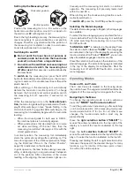
All three operating modes are possible with the meas-
uring tool in horizontal and vertical position.
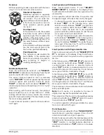
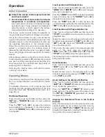
Rotational Operation
Rotational operation is especially
recommended when using the la-
ser receiver. You can select be-
tween different rotational speeds.
In the horizontal position and rota-
tional operation, precise grades
can be set.
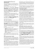
Line Operation
In this operation mode, the variable
laser beam moves within a limited
aperture angle. This increases the
visibility of the laser beam in com-
parison to rotational operation. You
can select between different aper-
ture angles.
In line operation with programmable
line, the start and end point of the
line can be specified individually.
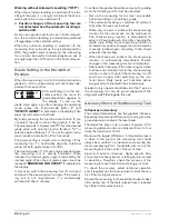
Point Operation
This operation mode enables the
best visibility of the variable laser
beam. As an example, it is used for
easy projecting of heights or
checking building lines.
Rotational Operation
Press the function-mode button
7
until
“SELECT/
ROTATION”
is indicated on the display. Press the left
selection button
8
to start rotational operation.
The current rotational speed (in min
-1
) is indicated
next to
“ROTATE”
(rotational speed). Set the desired
rotational speed with selection button
8
above
“FAST”
or selection button
4
above
“SLOW”
. The
rotational speed can be slowed down to 0 min
-1
(point
operation).
When working with the laser receiver, the rotational
speed should be set to at least 600 min
-1
. When
working without laser receiver, reduce the rotational
speed for improved visibility of the laser beam and use
the laser viewing glasses
21
.
To end rotational operation, press function-mode but-
ton
7
again.
Line Operation with Standard Line
Press function-mode button
7
until
“SELECT/
SWEEP SETUP”
is indicated on the display. Press
the left selection button
8
to start line operation with a
standard line.
In line operation with standard line, the position and
the aperture angle of the laser line can be changed.
– To change the position, press the selection button
8
above
“POS”
. In the following menu, press
selection button
8
above
“CCW”
(counterclock-
wise) or selection button
4
above
“CW”
(clock-
wise) to rotate the laser line to the requested
position within the rotational plane. To exit the sub-
menu, press function-mode button
7
.
– To change the aperture angle, press the selection
button
4
above
“LENGTH”
. In the following menu,
press selection button
8
above
“LONG”
or selec-
tion button
4
above
“SHORT”
to specify the aper-
ture angle of the laser line. To exit the submenu,
press function-mode button
7
.
Line Operation with Programmable Line
Press function-mode button
7
until
“SELECT/PT TO
PT”
is indicated on the display. Press the left selec-
tion button
8
to start line operation with a programma-
ble line.
In the following menu
“PTP:SET PT A”
(set point A),
press selection button
8
above
“CCW”
(rotation in
counterclockwise direction) or selection button
4
above
“CW”
(rotation in clockwise direction) to posi-
tion the left end point of the laser line. To exit the sub-
menu, press function-mode button
7
again.
In the following menu
“PTP:SET PT B”
(set point B),
press selection button
8
above
“CCW”
(rotation in
counterclockwise direction) or selection button
4
above
“CW”
(rotation in clockwise direction) to posi-
tion the right end point of the laser line. To exit the sub-
menu, press function-mode button
7
again.
The measuring tool now indicates a laser line between
both positioned points.
Note:
Due to inertia, it is possible for the laser to
slightly move beyond the specified end points.
The end points of the line can be changed by pressing
selection button
8
above
“PTP A”
(point A) or selec-
tion button
4
above
“PTP B”
(point B).
To end line operation with programmable line, press
function-mode button
7
again.
Point Operation
Press function-mode button
7
until
“SELECT/SPOT”
(selection/point operation) appears. Press the left
selection button
8
to start point operation.
Rotate the laser point within the rotational plane to the
desired position by pressing selection button
8
above
“CCW”
(rotation in counterclockwise direction) or
selection button
4
above
“CW”
(rotation in clockwise
direction).
OBJ_BUCH-971-001.book Page 24 Wednesday, August 12, 2009 8:46 AM
Summary of Contents for AL-Series
Page 2: ...2 2 610 A15 112 12 8 09 6 5 3 4 3 8 7 2 2 1 9 12 13 16 17 18 14 15 11 10 13 ALGR...
Page 3: ...3 2 610 A15 112 12 8 09 19 21 22 23 24 20 25 B A...
Page 4: ...4 2 610 A15 112 12 8 09 28 27 26 29 30 31 32 33 34 35 37 36 38 39 40 RC400X...
Page 155: ...E 155 2 610 A15 112 12 8 09 f f 10 f f 2 IEC 60825 1 f f UV f f f f f f f CST berger 23 f 23...
Page 158: ...158 E 2 610 A15 112 12 8 09 f f f 163 24 f f ON OFF 6 9 1 5 162 0 00 30 s 5 161 60 s ON OFF 6...
Page 163: ...E 163 2 610 A15 112 12 8 09 30 s 12 20 m 100 m 20 m 20 m Service Bosch 30 m 30 m 0 00 I 30 m...
Page 165: ...E 165 2 610 A15 112 12 8 09 5 8 13 13 5 8 B 24 5 8 13 24 24 15 cm 23 23 23 1 9...
Page 240: ...240 2 610 A15 112 12 8 09 f f 10 f f 2 IEC 60825 1 f f f f f f f f f CST berger 23 f 23...
Page 243: ...243 2 610 A15 112 12 8 09 f f f 248 24 f f 6 9 1 5 247 0 00 30 5 245 60 6...
Page 255: ...255 2 610 A15 112 12 8 09 Bosch 10 oe e e e oe e e e 251 252...
Page 256: ...256 2 610 A15 112 12 8 09 f f 10 f f 2 IEC 60825 1 f f f f f f f f f CST berger 23 f 23...
Page 270: ...270 2 610 A15 112 12 8 09 Bosch 10 C a a c ep i i i C a a c ep i i i 267 267...
Page 285: ...285 2 610 A15 112 12 8 09 f f 10 f f 2 IEC 60825 1 f f f f f f f f f CST berger 23 f 23...
Page 294: ...294 2 610 A15 112 12 8 09 22 600 min 1 25 3 25 297 5 8 13 13 24 5 8 13 24 24 15 cm 23 23 23...

