


4
www.csp-shop.de
[email protected]
Version: 10-18
© by CSP Products
-
Run the software, and you will see an elec-
tronic dashboard. In the top-center you will
see two grey tabs, with “Dashboard“ and
“Settings“.
-
By clicking “Settings“ you will see the page,
where you can edit your centrifugal and
vacuum advance curves, and where you
can “Store“ them into your CSP Products
Pacemaker USB distributor.
-
Click “Dashboard“ again, and you will see
the electronic dashboard again. Note the
red dot in the bottom-left corner. This indi-
cates that there is presently no connection.
-
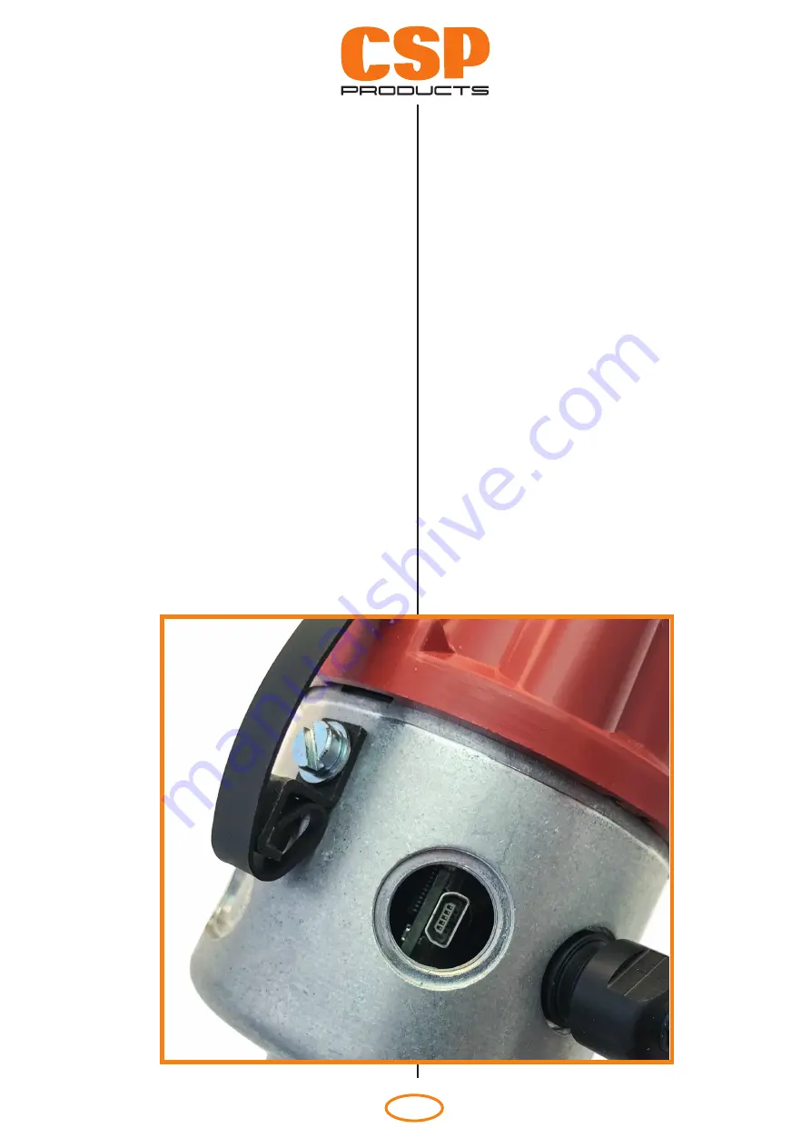
Now connect your CSP Products Pacemak-
er USB distributor with a USB wire. Therefor
remove the large screw on the distributor
body. The USB port is located behind it (Fig.
1). After connecting the distributor the dot
changes to green, accompanied by an audi-
ble signal. Please use shielded USB-cables
only.
-
Starten Sie das Programm. Ein elektro-
nisches Steuerfeld wird angezeigt. Mittig
oben sehen Sie zwei graue Registerkarten,
gekennzeichnet mit „Dashboard“ und „Set-
tings“.
-
Beim Klicken auf „Settings“ erscheint die
Seite, auf der man die zentrifugale und die
Vakuum-Kurve bearbeiten und unter „Store“
auf dem CSP Products Pacemaker Verteiler
speichern kann.
-
Klicken Sie noch mal auf “Dashboard“ und
das elektronische Steuerfeld erscheint
wieder. Der rote Punkt in der linken, unteren
Ecke zeigt an, dass momentan keine Ver-
bindung besteht.
-
Schließen Sie jetzt Ihren CSP Products
Pacemaker USB Verteiler mit einem USB-
Kabel an. Dazu entfernen Sie die große
Schlitzschraube am Verteilergehäuse. Da-
hinter befi ndet sich der Mini-USB-Anschluss
(Fig. 1). Nach dem Verbinden mit dem USB-
Kabel leuchtet jetzt der Punkt grün und ein
akustisches Signal ertönt. Bitte nutzen Sie
ausschließlich abgeschirmte USB-Kabel!
Fig. 1


