background image

7

gyro is a good time to check the condition of tail drive gears, belts, pulleys
etc. Inspect them regularly to ensure that they are in good condition.

Mounting the gyro

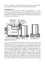
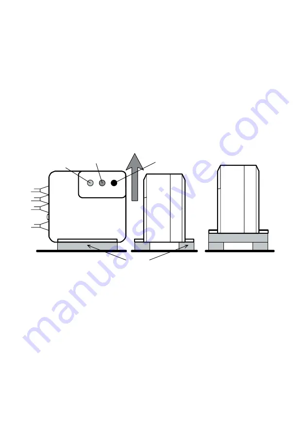
The gyro may be mounted lengthways (longitudinally) or across
(transversely) within the model however it should have its axis of rotation
(as marked on the back of the gyro case) parallel to the main shaft of the
helicopter. For setting up you will need to see the LEDs so mount the gyro
where these can readily be seen.

Axis of rotation

Make this parallel to the

Attach to helicopter using two of the self-adhesive foam strips provided

SERVO

RUD. IN

GAIN

PWR

REV

SL

560

GYRO

Power indicator LED

Gyro sense reverse LED

(red)

(yellow)

Mount gyro where 
these are visible

main shaft of the helicopter

Indicator LEDs

For high vibration environment
use four strips as shown.

SUPER

SERVO

Super Servo LED

(green)

PC

Figure 2. 

Gyro orientation

The gyro sensor (together with the electronics of the gyro) is anti-vibration
mounted inside the gyro case. However, to provide further vibration and
shock resistance it is important that the gyro be mounted to the airframe
using two of the double sided adhesive foam strips provided. Do not use
any other type of mounting foam as this will reduce the performance of
your gyro. Replacement strips are available as a CSM spare. For good
adhesion, ensure that the surface to which the gyro is attached is smooth,
hard and clean. As with all high performance solid state gyro systems, the
SL560 performs best if sited at a point of low vibration in the helicopter
airframe. Where possible avoid siting the gyro at the extreme front of the
radio tray for example as this area is often subject to high levels of main
rotor generated vibration. Also many plastic radio trays are too flexible and

Summary of Contents for SL560 GYRO

Page 1: ...N NEW Quick trim accurately corrects linkage set up N Built in Exponential gives a smooth progressive stick response N Yaw Rate Demand with rudder rates throws it gives you total control of stick sensitivity N Command conditioning removes stick bounce improves performance with PPM FM receivers N Acceleration Gain gives automatic dynamically adjusting gain tracking N Dual Independent Stop Tracking ...

Page 2: ... SL560 is obtained when it is used in conjunction with a high speed Super Servo or Digital Servo 0 1 seconds 60 degrees or less Use with slower servos will significantly reduce gyro performance Super Servos The term super servo is used to describe servos capable of running at high data frame rates 250 frames second or more Examples of this type of servo are Airtronics 94757 JR 8700G and Futaba S92...

Page 3: ...wag on an otherwise well set up helicopter You may wish to consider maintaining the charge in your receiver battery between flights by the use of a quality Delta Peak type field charger In installing the gyro also bear in mind that voltage losses down long servo extension leads will also detract from servo performance Where the installation requires extensions to be used either between the receive...

Page 4: ...SL560 on the ground may seem unusual Unlike conventional systems it is quite normal for the SL560 in Standard mode mode 0 to provide full tail rotor servo movement for rudder commands that are as little as 30 of the full stick movement This is a consequence of the Yaw Rate Demand feature and is why the SL560 gives such a crisp response With the helicopter on the ground and the SL560 set in Smart L...

Page 5: ...e initial hovering phase which is made even easier as this mode allows the tail trim to be set before the helicopter leaves the ground 2 For cross wind hovering manoeuvres where the natural tendency of the helicopter to weathercock into wind needs to be resisted 3 For backwards flight manoeuvres and general 3D flying The Standard mode may be employed for basic forward flight where the natural tend...

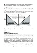
Page 6: ...ch Position Gyro Figure 1 The Gyro gain channel acts as both gyro mode switch and gain control Installation Preparing the helicopter mechanics Attention to the tail control linkage is important to getting the best from this gyro You should aim for an easy moving but slop free linkage between the tail servo and the tail blades Inspect the bearings thrust races in the tail hub for smoothness of oper...

Page 7: ...tion environment use four strips as shown SUPER SERVO Super Servo LED green PC Figure 2 Gyro orientation The gyro sensor together with the electronics of the gyro is anti vibration mounted inside the gyro case However to provide further vibration and shock resistance it is important that the gyro be mounted to the airframe using two of the double sided adhesive foam strips provided Do not use any ...

Page 8: ...separate adjustments for left and right movements and you should make sure you have set the travel adjustment for both directions At this stage i e before the gyro has been installed we are using this value to help establish the right servo arm length Once the gyro has been installed the rudder ATV is used to set the yaw rate demand N Ensure that the rudder rates are set to the default value of 10...

Page 9: ...full pitch linkage movement but avoids the linkage binding or the servo stalling Many helicopters have pitch systems that do not give equal throw about the hover pitch value The SL560 has independent servo throw adjustments for left and right which will accommodate this and fine tuning of the servo throw is done later in the Quick setup routine Rudder control sense N Now we must establish that the...

Page 10: ...power LED comes on approximately 5 seconds N Move the rudder stick and check that the servo swings both ways If it swings the same way for left and right stick movements you have the rudder and gain inputs of the gyro transposed Connect rudder and gain inputs correctly and repeat this test N We must now identify which gain switch position gives mode 0 and which gives mode 1 The flight modes can be...

Page 11: ... rotor servo operating sense has been correctly set in the transmitter Failure to do this will cause an uncontrollable pirouette on take off Beginners who are in any doubt on this aspect of the set up should seek advice N The correct operating sense can be established by looking at the tail rotor blades With a left tail rotor command held on the leading edge of the tail blades are pointing to the ...

Page 12: ...stick to the left and release it back to the middle This will set the gyro sense to match your system The servo will travel over to allow the user to check that left tail command is indeed being given and once this has been checked the gyro sense is entered by toggling the gain switch once i e into mode 0 and back to mode 1 The gyro will zip the servo back and forth in acknowledgement and again pa...

Page 13: ...urned off for about 5 seconds and turned on again At turn on the gyro takes approximately 5 seconds to re boot Having re started the system check the operation of the tail servo for rudder inputs and helicopter movements Do this for both flight modes It is important to check the gyro operating sense To do this simply set the gyro in mode 1 Smart Lock mode and rotate the helicopter 90 degrees to th...

Page 14: ...isable the JR code 44 gyro sense adjust and control the gyro gain by a switch In this case the gain for the two gyro modes is adjusted by the two travel adjustment values for the gyro channel Initial values of 60 should be used Set up with code 44 enabled If you wish the gyro to switch automatically between mode 0 and mode 1 as the Flight Mode Idle Up switch is operated you will need to enable the...

Page 15: ...le up positions in order to see the status for all the conditions see your ZAP ZHP manual for more detail First ensure that in all flight modes the gyro sense mode is set to INHIBIT To do this go to the GYR entry of the helicopter condition menu and for each flight condition press the INH key to select the INHIBIT state Then press END to exit the gyro sense menu Now check under the PMX entry that ...

Page 16: ...ent with settings until you are satisfied The rotation or pirouette rate will still be controlled by the use of EPA on the rudder channel and should be set to about 60 initially for both left and right throws This can be increased after flight testing if you require a quicker rotation rate The SL560 Quick setup routine can still be utilised by toggling the Flight Mode 1 switch a couple of times to...

Page 17: ...ut first we need to adjust the mode 0 trim with the Quick trim procedure Quick trim Note Even if you do not wish to fly in mode 0 it is important for optimum performance that you go through the Quick trim procedure The Quick trim facility allows the gyro to correct for imperfections in the mechanical adjustment of the tail pitch linkage While hovering in calm conditions switch to Flight mode 0 Sta...

Page 18: ... Should this be observed you should lower the gyro gain slightly Stop Optimisation Further improvement to the pirouette stop quality can often be gained by adjustment of the linkage geometry and the gyro s Stop Tracking controls and acceleration gain These are accessed by the PC interface Please refer to the PC interface manual for more detail Adjusting the stick response After initial setting use...

Page 19: ... movement without stalling the servo In most helicopters this will be an arm of between 15 and 20 mm radius Note As the servo travel limits are set during the Quick setup routine increasing the rudder travel adjustment will not increase the servo throw as this is limited electronically in the gyro The rudder travel adjustment is used instead to adjust the rotation rate Tail blade size The correct ...

Page 20: ...the longer the boom supports the better they will work Note A loose cracked boom support or a loose cracked boom support clamp can have a significant effect on the gyro gain Even a slightly loose boom clamp or support will have a dramatic effect on the amount of gain that can be used Stand on the skids of the model and try to flex the end of the boom from side to side while holding a finger agains...

Page 21: ...o use a battery state monitor and check it before each flight Do remove slop and stiffness from tail control linkage Do inspect tail gears etc for wear Do explore the performance limits of this gyro with care DON Ts Don t subject the gyro to mechanical shock Don t mount the gyro where it will be subjected to high vibration levels Don t use Pilot Authority Mixing Don t use Automatic Tail Stabilisat...

Page 22: ...flies OK in one gyro mode but wags when switched to the other mode You have too much gain in just the one mode Reduce the gain channel travel adjustment for the mode that wags Tail response is not crisp Too little gyro gain Gradually increase travel adjustment of the gain channel until tail shows some tendency to wag and then reduce it back until wag just stops Model wags even when the gain is ver...

Page 23: ...ed a high internal resistance Cycle the battery and check its capacity It may show a normal capacity at low discharge rates but a much reduced capacity when measured at say 3 amps discharge rate indicating a high internal resistance The left and right hand stops are not equal Stops from right hand turns are slow but clean while left hand stops are bouncy The mechanical tail trim needs setting corr...

Page 24: ...by CSM Design Consultancy Ltd For repairs and servicing please contact CSM Service Department Woodfield House Woodfield Rd Altrincham Cheshire WA14 4ED England Tel 0161 928 8505 Fax 0161 929 5984 EMail tech csm ltd co uk Distributed world wide by RC Models Distribution Ltd Woodfield House Woodfield Rd Altrincham Cheshire WA14 4ED England Tel 0161 929 5955 Fax 0161 929 5984 EMail sales rcmodels org...

Reviews: