background image

Page 42   


Crystal Engineering Corporation

.

X

User.Defined.Units


 nVision gives you the ability to create your own custom User Defined Unit 

based on pressure.


Implement your slope (user factor) and offset (offset factor) in


CrystalControl.


See


CrystalControl application and manual for details.

.

X

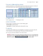
Pressure.Conversions

1 PSI =  27.6806 inches of water column (water at 4°C [39.2°F])


27.7070 inches of water column (water at 15.6°C [60°F])


27.7292 inches of water column (water at 20°C [68°F])


2.03602 inches of mercury (mercury at 0°C [32°F])


51.7149 millimeters of mercury (mercury at 0°C [32°F])


703.087 millimeters of water column (water at 4°C [39.2°F])


0.070307 kilograms per square centimeter


68.948 millibar


6.8948 kilopascals


0.068948 bar


0.006895 MPa

Summary of Contents for nVision Lab Reference Recorder

Page 1: ...C R Y S T A L engineering corporation Operation Manual Reference Recorder Lab Reference ...

Page 2: ...rding 8 Navigation Select buttons 8 Back button 8 Record button 8 Power button 9 Zero PM 9 Backlight button 10 Display Screens Numerical and Graphical 10 Numerical Display Screens Live and Live Recording Data 10 Peaks 11 Filter 11 Numerical Display Screen Differential Mode 12 Upper Lower and Tare 12 Graphical Screens Live Recording or Last Recorded Data 13 Viewing Graphical Screen Data in Detail 1...

Page 3: ...rential Reading 26 Upper and Lower Readings 26 Tare 26 Differential Readings 26 Measurement Uncertainties for two Pressure PM Modules using Tare Function 27 Measurement Uncertainties for two Pressure PM Modules without Tare 27 Measurement Uncertainties for two Temperature RTD100 Modules without Tare 28 Measurement Uncertainties for two Temperature RTD100 Modules with Tare 28 Module Installation In...

Page 4: ...al Pressure Mode 41 Logging Interval 41 Media Compatibility 41 Connection 41 User Defined Units 42 Pressure Conversions 42 Accuracies Ranges and Resolutions 43 Current Voltage Switch Test MA20 Specifications 44 Connection 44 Terminals 44 Logging Interval 44 Entity Parameters 44 Accuracy 45 Ranges Resolutions and Units 45 mA Input 45 HART mA Input 45 Accuracy 45 Ranges Resolutions and Units 45 Swit...

Page 5: ...t included in RTD100 52 Rack Mount Kit for nVision Lab Reference only 52 ATEX Safety Instructions 53 ČESKY Czech 53 DEUTSCH German 53 ENGLISH English 54 ESPAÑOL Spanish 54 FRANÇAIS French 55 ITALIANO Italian 55 NEDERLANDS Dutch 56 POLSKI Polish 56 SUOMEN KIELI Finnish 57 Troubleshooting 57 Noisy or unstable reading when used with fluids 57 Non repeatability of pressure measurements 58 Slow return ...

Page 6: ......

Page 7: ...y IP67 rated enclosure 1 meter immersion for 30 minutes nVision Reference Recorder only Uses Crystal s new CPF fittings and hose system leak free and finger tight to 10 000 PSI 700 bar We hope your nVision meets your expectations and we re interested in any comments or suggestions you may have You can send us a note at sales crystalengineering net Many features in this and our other products are a...

Page 8: ...lay backlight Adjust Backlight Shutoff Zero button Press to zero Pressure Module reading Hold for 3 seconds to clear any zero value Adjust Zero Limit Power Icon Key nVision Lab Reference Icon Description External Power AC Adapter USB Connection USB Connection is for data transfer only Power Icon Key nVision Reference Recorder Icon Description External Power USB 100 75 50 25 0 Power Remaining Repla...

Page 9: ...kly when recording ends Flashes when an overpressure condition occurs Record button Start Stop data recording Adjust Logging Interval Power button Turn your nVision on off Lower Module Bay Setup Button Locate additional features Clear Peaks Units Adjust Available units Settings Contrast Lock Unlock Chassis Summary Chassis Upper Lower Recording Start Stop Erase All Runs This icon represents a compo...

Page 10: ...igh Low Peak always measured at 10 readings per second Filter 20 reading moving window fixed Maximum Working Pressure Pressure Module Only Selectable Units via Setup button Vertical Scale Applied versus full scale pressure Numerical Dual Mode Screen Both Sensors Sensor Reading biased towards applicable module Upper Module reads higher on the screen Lower Module reads lower on the screen ...

Page 11: ...egardless of cursor location or zoom level Graphical Dual Mode Screen Both Sensors Navigating the Graphical Display In the graphical modes the nVision navipad enables you to control how you view your data Data Scroll Using the keys allows you to navigate to specific points along your run while displaying reading and time information Graph Zoom Using the keys allows you to zoom in and out of your r...

Page 12: ...nits Settings Summary and Recording Use the navigation button up down arrows to move to the desired feature and use the select or right arrow buttons to move into the desired function X X Clear Peaks Resetting Hi and Lo Peaks Peak values Hi and Lo can be cleared via the setup menu Press the setup button navigate to Clear Peaks with the up down arrows and use the select button to pick the desired f...

Page 13: ... event you lose the password you will need to contact the factory for an unlock code which will remove the password protection X X Summary Not sure of what modules or settings you have loaded in the nVision The Summary item al lows you to view valuable details or settings in your chassis or module To view a specific mod ule summary you will need to choose Chassis Upper Module or Lower Module Items...

Page 14: ...th the nVision To start LEDs solid or stop LEDs flash a recording run from any screen simply press the record button for one second Record ing logs all the available data so even if you are viewing the lower module numerical display the upper data will be recorded and available for CrystalControl downloading viewing and archiving The recording or Logging interval of your nVision can be viewed in t...

Page 15: ...imer will not shut off your nVision while recording When powered by USB the nVision does not employ any power management strategies There fore it will not automatically shut off to the settings defined by CrystalControl CAUTION Never remove power when Recording Zero PM To zero the nVision you must press the button for at least 1 second The display will then briefly flash all dashed lines indicatin...

Page 16: ...ecorded into the 500 000 data point memory capacity 3 Last Recorded This is previously recorded data available for viewing Note that you may view all the previously recorded data in CrystalControl but only the last recorded run on the nVision chassis Numerical Display Screens Live and Live Recording Data The nVision numerical screens allow you to view live or live recording data in a traditional w...

Page 17: ...ilter values are not saved when the gauge shuts off they will reset to the current reading when the nVision is turned on or reset X X Peaks Hi and Lo readings are useful for seeing rapidly changing events such as pressure during a relief valve test or longer duration events such as measuring pressure and temperature during pipe line hydrostatic testing Hi Maximum recorded reading Lo Minimum record...

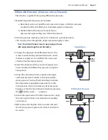
Page 18: ...th the Upper and Lower readings in this mode are filtered with a fixed twenty 20 sample window that offers a dampened view of your data Additionally it also contains a Tare function that allows you to equalize the upper and lower sensor readings To clear the Tare value in Differential Mode hold the button for 3 seconds until the main display readings change from to Upper Filtered live reading of u...

Page 19: ...ecording run REC icon is present Lower Module Graphical Screen The upper module data will also have its border wrapping around the top for identification purposes The following is a representative screen from a temperature RTD100 module located in the upper bay Upper Module Graphical Screen If you desire to view both the upper and lower graphical displays simultaneously the dual view is also possi...

Page 20: ...ed run As you move the cursor with the right left arrow keys you will notice the time stamp changing in the lower right hand box This is the time stamp of the specific data point corresponding to the cursor location and reading If you are searching for a specific measurement within your recorded test use the cursor readings or time stamp to locate the required information Return the cursor to the ...

Page 21: ...timer enabled When the timer elapses a power savings screen will appear as shown To return to normal operation simply press any key Battery Replacement The nVision uses 4 AA batteries Unscrew the four captive screws knurled Phillips head to gain access to the battery compartment Replace the batteries taking care to note polarity for their proper installation After replacing the batteries and reins...

Page 22: ... SELV or Protective Extra Low Voltage Circuits PELV See the nVision Product Speci fications for a complete description of SELV and PELV The USB connector has an Um of 6V Reset If for some reason the nVision needs to be reset remove the battery pack for at least one minute then reinstall If the reset is successful the nVision will start operating without pressing the button when the power pack is r...

Page 23: ...unit As shipped from the factory the nVision is set to display inches of water corresponding to the density of water at 4 C 39 2 F You may require a different water density for your application CrystalCon trol allows the user to select the appropriate water density desired at 4 C 39 2 F 20 C 68 F or 15 6 C 60 F temperatures Overpressure Conditions The nVision will read pressure up to approximately...

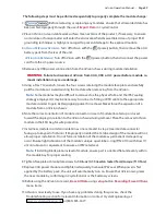
Page 24: ...al of the source 5 Power up circuit and measure or record the readings as appropriate 6 Never change modes or electrical sources without first removing the nVision from the circuit Failure to do so may damage the nVision WARNINGS The following warnings apply to the MA20 module Never install two 2 MA20 modules simultaneously This configuration may permanently damage your nVision Never exceed the ma...

Page 25: ...mA Select the desired current mode through the Setup menu to properly configure the nVi sion prior to connection and use The illustration denotes the proper current measurement connec tion scheme to the MA20 module X X Current Measurement with HART Resistor The nVision may be used to measure current in a circuit that includes a HART transmitter or device For devices that use the HART protocol a lo...

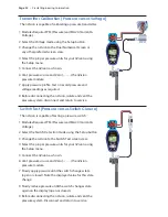
Page 26: ...ule With this system you may connect your platinum resistance thermometer to the nVision using the provided IP67 rated connector system P N 3953 Once the sensing ele ment is connected you may display the temperature reading in your desired unit The nVision can also measure electrical resistance Ω to help in troubleshooting your resistance based sens ing element Temperature Coefficient of Resistanc...

Page 27: ...ollowing sources of supply may be used a Phoenix Contact i Order Number 1501265 or Part Number SACC M8MS 4CON M SM b Binder i Part Number 99 3383 100 04 3 RTD sensor element cable preparation a Strip approximately 12 0 mm 0 5 in outer insulation from RTD cable b Strip the individual RTD element sense wires approximately 4 0 mm 0 16 in c Install 3 piece sealing system see Figure 1 below onto the ca...

Page 28: ...mance of your sensor This feature can be found in CrystalControl and can also be viewed under the Summary pages on the nVision product Resistance Temperature Detectors RTDs Resistance Temperature Detectors RTDs are temperature sensors that contain a resistor that utilize the predictable change in electrical resistance of particular materials over temperature Platinum elements have been used for ma...

Page 29: ...fied with CrystalControl to achieve the method that you prefer See Temperature Module RTD100 Specifications for further information Callendar Van Dusen Equation The relationship between temperature and resistance is given by the Callendar Van Dusen equation RT R0 1 AT BT2 CT3 T 100 for 200 C T 0 C RT R0 1 AT BT2 for 0 C T C of Upper Temperature Range listed below Where RT the resistance at tempera...

Page 30: ...mperature Deviation Accuracy at 0 C Standard Class A 0 15 0 002 t C 100 00 0 06 Ω DIN IEC751 Class B 0 3 0 005 t C 100 00 0 12 Ω DIN IEC751 1 Crystal Engineering recommends combining system expanded uncertainties in accordance with recommendations out lined in ISO Guide to Expression of Uncertainty in Measurement GUM The uncertainties typically reported by Crystal Engineering represent expanded un...

Page 31: ...ects to the other side The two adjoining lead wires cancel each other out allow ing the nVision to read the RTD sense element without the associated lead resistance measure ment error This self canceling resistance value is also subtracted from the other leg with the assumption that the two are equal Your nVision is also capable of 4 wire measurements The fourth wire allows the other side of the l...

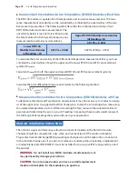
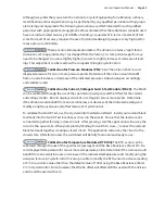
Page 32: ...P reading may have a value other than zero The Tare function allows you to normalize both of these readings so that the P reading is zero Therefore you will have a much more accurate P reading than you normally would have if this process was not completed The Tare should be reestablished every time you are at a new static line pressure including vent condition For instance if your P reading has 8 ...

Page 33: ...0 10 1 10 0 0001 0 00001 0 001 0 01 0 001 0 00001 0 01 300 30 3 30 0 001 0 0001 0 001 0 01 0 01 0 0001 0 1 0 00001 1 000 100 10 100 0 01 0 0001 0 01 0 01 0 01 0 0001 0 1 0 00001 3 000 300 30 300 0 01 0 001 0 01 0 1 0 001 0 0001 10000 700 70 700 0 1 0 001 0 1 0 001 0 0001 X X Measurement Uncertainties for two Pressure PM Modules without Tare The total nVision Reference Calibrator measurement uncert...

Page 34: ...certainties it may be necessary to conduct an analy sis of the application A suggested method of analysis is to Tare the T reading when measuring the isolated temperature at site A Without resetting the Tare measure the isolated site B tem perature and determine the error in your T reading Comparing these results would represent the full range of t readings that you would see in your application M...

Page 35: ... gain better gripping power for removal Never force the separation of a module from an nVision chassis 6 Note the correct orientation of module connector on rear of module located up or closest toward the display in relation to the nVision chassis during removal Place the removed nVision module in the ESD bag for safe protection 7 Install new module in similar orientation as one removed in step 2 ...

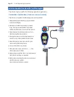
Page 36: ...libration Pressure versus Current section 3 Select desired Current mode mA or 4 20mA using the Setup button 4 Change the nVision to the Dual Numerical Screen or any other preferred screen view 5 Select the proper pressure units for your nVision using the Setup menu 6 Connect the nVision as shown 7 Vent pressure source and Zero the nVision pressure module 8 Apply pressure profile Test or record pre...

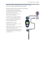
Page 37: ...urrent mode mA or 4 20mA using the Setup button 4 Change the nVision to the Dual Numerical Screen or any other preferred screen view 5 Select the proper pressure units for your nVision using the Setup menu 6 Connect the nVision as shown 7 Vent pressure source and Zero the nVision pressure module 8 Apply pressure profile Test or record pressure and current readings as required 9 Before disconnectin...

Page 38: ...eturn to service Switch Test Pressure versus Switch Closure The nVision is capable of testing a pressure switch 1 Modules Required PM Pressure and MA20 Current Voltage 2 Select the Switch Detection mode using the Setup button 3 Change the nVision to the Switch Test screen view 4 Select the proper pressure units for your nVision using the Setup menu 5 Connect the nVision as shown 6 Vent pressure so...

Page 39: ... screen is automatically activated when two similar modules are present You will find this screen just after the Dual Numerical Screen 4 Select the desired units for your static upper and lower module and differential pressures using the Setup menu 5 Using the valve setup shown equalize the upper and lower pressure modules to the downstream static pressure You may find it beneficial to isolate thi...

Page 40: ... for quality measurements 6 Move your RTD100 sense elements to your target locations ex source A and B and take or record temperature readings as necessary 7 Before disconnecting the nVision isolate disconnect and return to service Calibration If adjustment is required we recommend returning the nVision or separate modules to the fac tory Factory service offers benefits you won t find anywhere els...

Page 41: ...actor userspan and the Offset for the current and voltage modes Record displayed current or voltage for two or more points Determine if the nVision would benefit from an overal increase or decrease of the indicated reading and modify using the userspan and offset feature of CrystalControl To calibrate the Switch Test use the CrystalControl Calibration Wizard Install your red and black test leads i...

Page 42: ...han 100 mA WARNING The mini USB B connector shall not be used within the hazardous atmosphere It shall be used in the non hazardous atmosphere with either Safety Extra Low Voltage Circuits SELV or Protective Extra Low Voltage Circuits PELV The USB connector has a Um of 6V SELV and PELV definitions per IEC60079 11 are Safety extra low voltage SELV Extra low voltage system i e normally not exceeding...

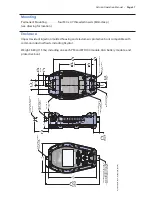
Page 43: ...BATTERY 100 2 88 ACCESS 73 BATTERY 20 0 79 MINI USB B ACCESS FLAP 2 41 60 MEDIUM PRESSURE FEMALE MPF 1 4 MEDIUM PRESSURE TUBE SYSTEM WITH 7 16 20 INTERNAL THREADS PRESSURE MODULE PM SHOWN CRYSTAL CPF SYSTEM RTD100 MODULE SHOWN WITH INCLUDED PROTECTIVE CAP 7 08 178 110 4 38 204 MAXIMUM WITH TWO PRESSURE MODULES 8 05 Mounting Permanent Mounting four M4 x 0 7 threaded inserts 8mm deep see drawing for...

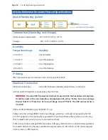
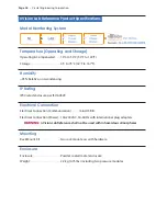
Page 44: ...non condensing IP Rating IP40 rated enclosure per ISO 60529 Electrical Connection Electrical Connection Communication mini USB B Electrical Connection Power 100 240VAC 50 60 Hz with international plug adapters WARNING nVision Lab Reference shall not be used within hazardous atmospheres Mounting Rack Mount Kit two rack mount ears with hardware Enclosure Enclosure Powder coated metal enclosure Weigh...

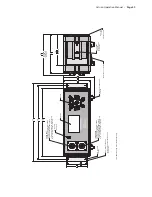
Page 45: ...H 7 16 20 INTERNAL THREADS 1 4 MEDIUM PRESSURE TUBE SYSTEM MEDIUM PRESSURE FEMALE MPF 4 PLACES 1 4 MEDIUM PRESSURE TUBE SYSTEM LOWER PORT PRESSURE MODULE PM SHOWN CRYSTAL CPF SYSTEM PANEL MOUNT FLANGES INCLUDED IN CRYSTAL ENGINEERING KIT P N 4302 10 9 276 80 3 2 256 10 1 11 4 291 116 4 6 103 4 1 68 2 7 FRONT FEET TILT FEATURE MODULES 5 9 5 6 143 WITH TWO PRESSURE 150 MAXIMUM 120 MAXIMUM 4 7 SET SC...

Page 46: ...eresis repeatability tempera ture and stability within the specified operating temperature range for one year Exposure to environmental extremes of temperature shock and or vibration may warrant a more frequent recertification period Pressure Module PM Specifications X X Accuracy 30 to 100 of Full Scale 0 025 of Reading 0 05 of Reading or 0 1 of Reading 0 to 30 of Full Scale 0 0075 of Full Scale 0...

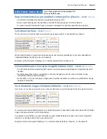
Page 47: ...al Fastest Logging Interval 10 readings per second X X Media Compatibility Liquids and gases compatible with sensor and CPF fitting system Wrench tight 316 Stainless Steel Finger tight 316 Stainless Steel and Viton internal MPF o ring X X Connection Crystal CPF System Medium Pressure Female MPF 1 4 medium pressure tube system with 7 16 20 threads See Crystal Engineering s CPF Brochure for further ...

Page 48: ... and manual for details X X Pressure Conversions 1 PSI 27 6806 inches of water column water at 4 C 39 2 F 27 7070 inches of water column water at 15 6 C 60 F 27 7292 inches of water column water at 20 C 68 F 2 03602 inches of mercury mercury at 0 C 32 F 51 7149 millimeters of mercury mercury at 0 C 32 F 703 087 millimeters of water column water at 4 C 39 2 F 0 070307 kilograms per square centimete...

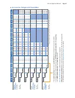
Page 49: ... 0 1 0 1 0 001 0 0001 10MPA 2 0 x 0 1 0 001 0 0001 100KG 2 0 x 0 1 0 001 0 1 0 1 0 001 0 0001 3KPSI 1 5 x 0 1 0 01 0 1 1 0 01 0 001 300BAR 1 5 x 0 1 0 01 0 1 1 0 01 0 001 30MPA 1 5 x 1 0 01 0 001 300KG 1 5 x 0 1 0 01 0 1 1 0 01 0 001 10KPSI 1 5 x 1 0 01 1 0 01 0 001 700BAR 1 5 x 1 0 01 1 0 01 0 001 70MPA 1 5 x 1 0 01 0 001 700KG 1 5 x 1 0 01 1 0 01 0 001 Density of water can be set to 4 C 60 F or ...

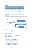
Page 50: ...Logging Interval Fastest Logging Interval 6 readings per second X X Entity Parameters The MA20 Module has these specific input entity parameters Ui 28 V Uo 6 6 V li 93 3 mA lo 4 45 mA Pi 653 3 mW Po 7 34 mW Ci 0 36 uF Co 0 5 uF Li 39 1 uH Lo 12 uH Total cable inductance between all modules Dependent on the supply to the terminals but shall not be greater than 0 5 uF MA20 Functional Diagram mA HART...

Page 51: ...on 0 001mA or 0 00 Units mA 4 20 X X mA Input Input Resistance 17 2 Ω Voltage Burden 20mA 0 35 V X X HART mA Input HART Resistance 250 Ω Voltage V Input X X Accuracy 0 015 of reading 0 002VDC X X Ranges Resolutions and Units Range 0 to 28VDC Max Allowable Voltage 30VDC Resolution 0 001VDC Units VDC Switch Test X X Switch Detection Switch States Dry Contact Closed State Resistance 10 Ω Open State R...

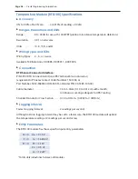
Page 52: ...k connector equivalent to Phoenix Contact Order Number 1501265 or Part Number SACC M8MS 4CON M SM or Binder P N 99 3383 100 04 Cable Diameter 3 5 to 5 0mm 0 14 to 0 012 in with smooth continuous covering adequate for IP67 sealing Stranded Conductor Cross Section 0 14 to 0 5mm2 0 0002 to 0 0008 in2 X X Logging Interval Fastest Logging Interval 2 readings per second Although nVision logging interval...

Page 53: ...ther models are equivalent The nVision can be operated and powered from the mini USB serial interface Warning Do not use the mini USB serial interface in a hazardous atmosphere Battery Life 200 hours typical 1 reading per second recording auto shutoff 20 minutes Settings such as Auto Shutoff Logging Interval and Backlight Shutoff greatly vary battery life The nVision screen display has the followi...

Page 54: ...Circuits SELV or Protective Extra Low Voltage Circuits PELV The USB connector has an Um of 6V Substitution of components may impair intrinsic safety Replace batteries with approved type in non hazardous locations only Parts of the enclosure may generate an ignition capable level of electrostatic charge under certain extreme conditions The user should ensure that the equipment is not installed or u...

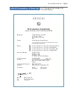
Page 55: ... T4 Ga Ta 20C to 45C Duracell MN1500 II 1 G Ex ia IIB T3 Ga Ta 20C to 50C Energizer E91 EN91 II 1 G Ex ia IIB T3 Ga Ta 20C to 50C Duracell MN1500 Harmonized Standards EN 60079 0 2006 7 0 0 2 1 1 9 7 0 0 6 N E 7 0 0 2 6 2 9 7 0 0 6 N E e c n a d i u G g n i k r a M 7 0 0 2 0 9 7 0 0 6 C E I EC Type Examination Certificate Sira 09ATEX2008X Issue No 1 Sira Certification Service Notified Body 0518 Rak...

Page 56: ...ssified as pressure accessories per guideline 1 6 have a volume V of less than 0 1 liter Article 3 1 1 a first indent Group 1 fluids Maximum Allowable Pressure PS 200 bar 2 900 psig All pressure gauges calibrators and reference recorders for use on gases or liquids below 200 bar 2 900 psig are not subject to the essential requirements of the directive 97 23 EC PED Annex I will be classed as Sound ...

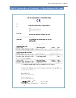
Page 57: ...t Voltage Module MA20 s s a P B s s a l C s n o i s s i m E d e t a i d a R 3 0 0 2 1 1 R P S I C EN 61326 1 2006 EN 61000 4 2 2009 Electrostatic Discharge Criteria A Pass EN 61326 1 2006 EN 61000 4 3 2006 RF Radiated Immunity Pass Temperature Module RTD100 s s a P B s s a l C s n o i s s i m E d e t a i d a R 3 0 0 2 1 1 R P S I C EN 61326 1 2006 EN 61000 4 2 2009 Electrostatic Discharge Criteria...

Page 58: ...djust base resistance RTD100 and select lead type methodology RTD100 Accessories Replacement Parts Soft Carrying Case included P N 4087 Durable padded case with separate pockets for your nVision and accessories Protective Boot included P N 3985 Skydrol resistant protective boot Blue USB A to mini USB B Cable included P N 3951 6 1 8m USB A to mini USB B Cable Warning Do not use USB interface within...

Page 59: ...EUTSCH German Die USB Schnittstellenverbindung darf niemals in einer explosionsgefährdeten Umgebung benutzt werden Der Batteriewechsel muß ausschließlich in sicherer Umgebung mit den vom Hersteller vorge schriebenen Batterie Typen erfolgen Der Benutzer ist für den richtigen Umgang des Digitalmanometers in explosions gefährdeter Umge bung verantwortlich Vom Hersteller vorgeschriebene Batterien DEUT...

Page 60: ...PAÑOL Spanish No use el conector USB en zona clasificada Cambie las pilas en zona no clasificada solo con pilas aprobadas Es responsabilidad del usario comprender la aplicación de este producto en atmósferas potencial mente explosivas Pilas aprobadas ESPAÑOL Spanish El nVision solo es intrínsecamente seguro si se alimenta con uno de los siguientes tipos de pilas Se han probado muchos otros tipos d...

Page 61: ...fere potenzialmente esplosive Batterie Approvate ITALIANO Italian L nVision è a Sicurezza Intrinseca solo se alimentato da uno dei seguenti tipi di batteria Molti altri tipi e modelli di batteria sono stati testati ma non sono risultati conformi alle richieste per Sicurezza Intrinseca non supponete che altri modelli siano equivalenti La batteria Energizer è fabbricata da Energizer Holdings Inc e E...

Page 62: ...s Inc en de Eveready Battery Company Inc Instrukcja Bezpieczeństwa Dla Srefy Zagrożonej Wybuchem POLSKI Polish Połączenie USB może być używane tylko poza strefą zagrożenia wybuchem Wymiana baterii tylko poza strefą zagrożenia wybuchem używaż tylko zatwierdzony typ baterii Odpowiedzialnością użytkownika jest używanie tego produktu we wlaściwy sposób w strefie zagrożonej wybuchem Zatwierdzone bateri...

Page 63: ...y Company Inc Troubleshooting The nVision is a very high performance reference recorder Due to the high resolution of this product you may observe conditions that appear to be defects in the product but are in fact a result of being able to read and measure pressure to a degree not possible with other instru ments Noisy or unstable reading when used with fluids When calibrating or comparing the in...

Page 64: ... on If any coefficients have been corrupted in any way Error 1 is displayed Solution Contact factory for instructions on how to restore the memory to the original factory settings Error 2 displayed Reason The nVision has tried to display a number too large for the display i e more than 6 digits May be due to an electrical malfunction or numerical error Solution Contact factory for further instruct...

Page 65: ... Eveready Battery Company Inc Pressure is Our Business is a registered trademark of Crystal Engineering Corp Service and Support How to Contact Us Phone 805 595 5477 Toll Free 800 444 1850 Fax 805 595 5466 Email service crystalengineering net Web www crystalengineering net If calling have ready the model number serial number date of purchase and reason for return You will receive instructions for ...

Page 66: ...was caused by misuse alteration accident or abnormal condition of operation you will be billed for the repair CRYSTAL ENGINEERING CORPORATION MAKES NO WARRANTY OTHER THAN THE LIMITED WARRANTY STATED ABOVE ALL WARRANTIES INCLUDING IMPLIED WARRANTIES OF MER CHANTABILITY OR FITNESS FOR ANY PARTICULAR PURPOSE ARE LIMITED TO A PERIOD OF ONE 1 YEAR FROMTHE DATE OF PURCHASE CRYSTAL ENGINEERING SHALL NOT ...

Page 67: ......
Page 68: ...PN 4116 Rev E C R Y S T A L engineering corporation 2010 Crystal Engineering Corporation 708 Fiero Lane Suite 9 San Luis Obispo California 93401 8701 ...

Reviews: