background image

05

06

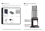
Power indicator

WiFi connection 

indicator

MODE indicator

Rj45 interface

This port is connected to the power adapter (SPEC: 5.5mm; 
“positive inside and negative outside icon”)

1. DC IN:

Connection supports RJ45 interface devices

2. Rj45 interface:

Rocker switch controls power on or off

3. Power switch:

Press the WPS button of both modules (set to AP/STA mode, 
respectively) at the same time, and the two modules will 
automatically establish a connection.

4. WPS button:

Press this button for about 5s and the module will return to the 
factory settings.

5. RESET button:

Steady on: The power is normal;

6. Power indicator:

Off: The power is off or abnormal.

Blinking: WIFI does not establish a connection
Steady on: WIFI connection is successful

Display the module operating mode

7. MODE indicator:

8. WIFI connection indicator:

Summary of Contents for 6689

Page 1: ... 6689 2019 04 06 User Manual Model 6689 Professional Wi Fi Adaptor Version 1 0 ...

Page 2: ......

Page 3: ...risen in the wiring process such as high wire cost and short service life If the on site protection is not enough the trampling of the passing crowd may affect the performance of wire and even cause a live broadcast accident 6689 provides a more convenient and safe solution for live video scenes Its long distance transmission coupled with the high capacity lithium battery system and PNP configurat...

Page 4: ... unpacking If any parts are missing contact the dealer For the parts involved in each model refer to the packing list below Wireless high speed data transmitter 6689 1 piece Base 1 piece Antenna 4 piece Network cable 1 piece Power adapter 12V 2A 1 piece Structure Interface Packing List RESET button WPS button Power switch ...

Page 5: ...ess the WPS button of both modules set to AP STA mode respectively at the same time and the two modules will automatically establish a connection 4 WPS button Press this button for about 5s and the module will return to the factory settings 5 RESET button Steady on The power is normal 6 Power indicator Off The power is off or abnormal Blinking WIFI does not establish a connection Steady on WIFI co...

Page 6: ...r respectively Since the Wi Fi is bidirectional the two ends can be exchanged arbitrarily without distinguishing between transmitting and receiving Webcam 2 Turn on the power switches of the camera and this product 3 Wait for 30 60s After the network connection indicator changes from blinking to steady on the connection is established successfully 4 Access the webcam from the PC Laptop ...

Page 7: ... The device on the other end is not electrified No pairing settings T oo far away The device is not electrified check whether the power indicator is on Turn on the device Wait for 30s after booting it takes time to start the system Turn on the device Perform pairing Shorten the distance between two devices The device functions abnormally Restart the device power 6689 Item STA AP Indicator Descript...

Page 8: ...1 After the device is booted connect the device to the computer with a network cable Open your browser on your computer Enter the IP address of the device in the address bar AP default IP address is 192 168 1 100 STATION factory default IP address is 192 168 1 200 After entering the login page enter the username and password both username and password are super by default to enter the menu page As...

Page 9: ...evice B in the WDS setting of device A and the Wireless MAC address of device A in the WDS setting of device B so that the two devices can be connected WDS Config Page Similarly if you want to continue adding cascaded device C you can add the Wireless MAC address of the device C in the WDS setting of device B and the Wireless MAC address of the device B in the WDS setting of device C 1 Cascading w...

Page 10: ...r its IP address is logged in through the WEB select wireless under config and click Device Mode to select between AP and STA modes 2 During mode switching the product is changed either from AP mode to STA mode or from STA mode to AP mode through this option After making changes click Save to save After saving successfully wait for 2min then refresh the page and log in again you can see that the m...

Page 11: ...clicking CVW001 AP CVW001 Passphrase will pop up After entering the password 12345678 click connect 5 After waiting for 1min refresh the page You can see that the ESSID is CVW001 indicating that the AP with the SSID of CVW001 has been successfully paired Note If you have two products at the same time and both have been set to AP STA mode separately they will automatically establish a connection by...

Page 12: ...ption When the wireless transmission distance is 200m in the open environment the LNA can be set to low gain mode In case of the need of wall penetration and the distance beyond 200m consider setting the LNA to high gain mode Product Software Upgrade 1 After the IP address of the product is logged in through the WEB select Upgrade under System 2 After selecting software upgrade under Choose a file...

Page 13: ...cur in a particular installation If this equipment does cause harmful interference to radio or television reception which can be determined by turning the equipment off and on the user is encouraged to try to correct the interference by one or more of the following measures Reorient or relocate the receiving antenna Increase the separation between the equipment and receiver Connect the equipment i...

Page 14: ......

Reviews: