Crystal Instruments Coco-80 Quick Reference Download Page 44


                                                                       CoCo-80 Quick Reference 


40 


Figure 40: Delete Database dialogue box 

New or Change Database 

Opens the Database Access Wizard, where different 
database can be accessed or a new database can be 
created. This is the same as pressing the 

Access

 button in 

the EDM Ribbon toolbar. 

Load Demo Database 

This will load a small database with sample 
measurements. Use this to learn to navigate through a 
Factory, add and delete elements, and view data. 
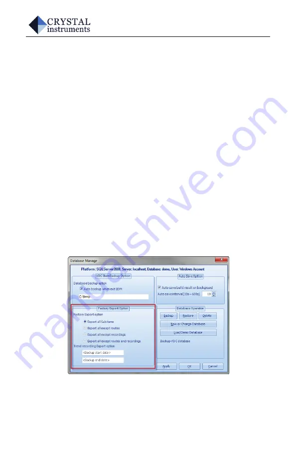
Factory Management 

Export a Factory 

Before exporting a Factory, set the 

Factory


Export


Options

. Click 

Manage

 from the ribbon bar, and set the 

options in the lower left of the 

Manage

 window. 


Figure 41: Factory Export Options 

This option specifies which items get backed up when a 
Factory is exported.  Note that when more items are 

Summary of Contents for Coco-80

Page 1: ...CoCo 80 Quick Reference Vibration Data Collector Mode 7 24 2012 Crystal Instruments Corporation 2370 Owen Street Santa Clara CA 95054 USA www go ci com 1 408 986 8880...

Page 2: ...d for general users Copyright 2012 Crystal Instruments Corporation All rights reserved This document or parts thereof may not be reproduced in any form without the express permission of Crystal Instru...

Page 3: ...Where is My License Key 9 USB Device Driver 10 CREATING A DATABASE 15 Accessing a New Database 15 Creating Database Items Factories Machines Points Entries and Routes 16 Adding Measurement Points 21...

Page 4: ...kup a Database 39 Restore a Database 39 Delete a Database 39 New or Change Database 40 Load Demo Database 40 Factory Management 40 Export a Factory 40 Import a Factory 44 COCO MEASUREMENTS 47 Select M...

Page 5: ...on EDM uses Microsoft Word for generating reports which should be installed on your computer prior to the installation of EDM EDM does not include Microsoft Word in its installation files EDM Software...

Page 6: ...te Administrator privileges are required for installation Please contact your IT department for information regarding installation of applications SystemRequirements Hardware Memory 512 MB o 1 GB reco...

Page 7: ...EDMSoftwareCD Engineering Data Management EDM is PC software used for data management post signal processing viewing reporting and connecting Crystal Instruments hardware the PC and the data storage s...

Page 8: ...ting the physical drive with the CD opening the EDM folder and double clicking on Setup exe Figure 1 Welcome Screen for EDM Installation CD Prior to installing EDM MSSQL needs to be installed on the s...

Page 9: ...re 2 EDM Installation Wizard Click Next to begin the installation process Review and accept the license agreement and click Next To install EDM a valid license key is required If the default location...

Page 10: ...ess There is no input necessary during the MSSQL installation Important Do not close any windows during the MSSQL installation Note Having the computer and a user account named the same can cause logi...

Page 11: ...he Start Menu Specify a name for this folder and press Next Select your preferences for Shortcuts Default Units Default Language Paper Size and Multiple Module support These setting can be changed lat...

Page 12: ...nce of EDM to run multiple Crystal Instruments devices A typical management page for license keys is shown in Figure 4 Figure 4 License Key Manager Software Renew Period this is the time period that t...

Page 13: ...M Installation CD 2 When the EDM Software and CoCo are shipped from Crystal Instruments an automated email message will be sent providing shipping information the License Key and the Serial Number of...

Page 14: ...able the USB driver must first be installed The driver does not install automatically To install it manually connect CoCo to the PC with the provided USB cable and power the CoCo on This cable has a m...

Page 15: ...on the computer Since the CoCo does not have a driver installed it should appear under the Other Devices heading as Generic RNDIS PROTOTYPE Remember to Change idVendor Double click on this entry to o...

Page 16: ...CoCo 80 Quick Reference 12 Figure 9 CoCo Properties window Select Browse my computer for driver software Figure 10 Device Driver installation window...

Page 17: ...ver Highlight this folder and click Select Press Next to scan that folder for the driver Figure 11 Browse for the location of the CoCo driver When Windows finds the driver it will alert that the drive...

Page 18: ...ence 14 Windows will apply the driver software Click Close when then installation confirmation window opens Figure 13 Notification of a successful driver installation The CoCo driver has now been succ...

Page 19: ...base must be created All data that is collected by the CoCo and analyzed in the EDM software is stored in a database on the PC Multiple databases can be maintained for different factories ships buildi...

Page 20: ...ture in the Database Explorer CreatingDatabaseItems Factories Machines Points EntriesandRoutes The Database Explorer displays the structure of the Database on the top half The view can be expanded and...

Page 21: ...convention of Factories Machines Points Entries and Routes A Factory can also be thought of as a physical area within a plant or perhaps a building The EDM database is not limited in the number of top...

Page 22: ...mode selects which Factory to work with Under the Factory structure will be a list of Routes that can be selected for use in data collection When a Database item such as a Factory Machine Point or Ro...

Page 23: ...ry the highest level must be highlighted If a button is disabled it is because that item cannot be add at this level For example when a new Machine is selected the Add a New Factory button is disabled...

Page 24: ...n be done this either by double clicking on the item or by selecting it and clicking on the Edit button on the toolbar Figure 19 Edit Entry button Similarly using the mouse and right clicking on an it...

Page 25: ...rch Peak Export Signal Data to File Delete Copy Machine Duplicate Machine New Reading Alarm Collapse All and Report Figure 20 Database Explorer pop up menu AddingMeasurementPoints Measurement Points a...

Page 26: ...ses the speed of the driven machine relative to its driven input speed this entry will account for the speed changes of the driven unit based on the tachometer reading or input at the time the measure...

Page 27: ...rement associated with a specific measurement Point One or more measurement Entries can be defined for any measurement Point For example an accelerometer can be used to take more than one type of meas...

Page 28: ...ter defaults entered in Parameter Set can be chosen or a new set can be created Figure 24 Measurement Entry settings window ExpectedRPM Ideally whenever a measurement is take a tachometer will provide...

Page 29: ...ter Set from the pull down menu or click New to create a new Parameter Set Parameter Sets specify the signals that will be computed the measurement quantity and the measurement interval The Customize...

Page 30: ...lect a Sensor Set from the pull down menu or click New to create a new Sensor Set Figure 27 Measurement Entry Wizard Sensor Set dialog Click Next to move to the last dialog Enter a name and descriptio...

Page 31: ...machine type can be duplicated and renamed to populate the database Not only does this make Factory setup quicker it also helps to insure that all measurement Entries are identical for each Machine of...

Page 32: ...e database is divided into multiple Areas moving from one Factory to another can be done easily in EDM or on the CoCo Click on the Add a Route button on the toolbar or double click an existing Route t...

Page 33: ...e cursor is to the left of the number the point will be moved as a heading of its own If the mouse is to the right of the number it will be added as a sub Point to what is directly above the line Righ...

Page 34: ...include the Replace mode option This will replace the entire Factory in the CoCo with the new Factory and Routes that are associated with that Factory For example if Machine 3 on the factory floor is...

Page 35: ...nes Points Entries and Routes have been defined in a Database it is ready to upload to the CoCo The backup options in the Database Management should also be checked to be sure that the database is sav...

Page 36: ...function the data must be downloaded to EDM for further analysis post processing and storage in the database DownloadfromVDCtoEDMwithNewMachineAdded Occasionally it may be necessary to add a new Machi...

Page 37: ...then connect the CoCo via USB or Ethernet and click the Download button in the EDM Devices Toolbar to start the Vibration Data Collector Synchronization Wizard Verify that CoCo Device is selected and...

Page 38: ...ialogue Select the Routes that need to be downloaded and press the Download button to transfer the data associated with those Routes Figure 34 Example of data selection window Once the transfer has co...

Page 39: ...k Download in the EDM Ribbon Bar to launch the Synchronization Wizard Figure 35 Synchronizing directly from an SD card Select File Folder Name is CoCo 80 and press Next To synchronize using this optio...

Page 40: ...ecify the CoCo 80 folder to synchronize with EDM Select the data to be synchronized with EDM and click Download Figure 37 List of available data When the transfer is complete click Finish to return to...

Page 41: ...to the database in a number of ways Figure 38 Manage Databases button The options below allow specify how and when the data is saved to the database Caution Data is not automatically saved into the da...

Page 42: ...ation AutoSave This option will automatically save the database based on the interval specified Auto save build result on background when this option is enabled then the database is automatically back...

Page 43: ...oreaDatabase Restore a database from a previously saved version The Restore VDC Database dialog will open Browse to the database file select it and then click the Open button DeleteaDatabase To comple...

Page 44: ...oDatabase This will load a small database with sample measurements Use this to learn to navigate through a Factory add and delete elements and view data FactoryManagement ExportaFactory Before exporti...

Page 45: ...udes all items except recordings Backup all except routes and recordings includes all items except route and recordings Trend recording backup options specifies the dates to include for trend recordin...

Page 46: ...ference 42 Figure 42 Factory Export option A window will open with the option to Include recording data and if selected a Date Range Recordings can also be included by selecting only Entries with a sp...

Page 47: ...port recording files options Once the settings for exporting data have been set press OK Figure 44 Set the location to save the Factory file Specify a name for the backup file and the location to save...

Page 48: ...ry from a file right click in the Database Explorer and select Import Factory Figure 45 Import Factory into a Database Browse for a Factory backup file in the window that opens Backup files have the e...

Page 49: ...automatically unless there is a duplicate Factory in the Database If there is a duplicate a window will open with the option to either Combine the Factories Replace the old factory or Keep Both Factor...

Page 50: ...CoCo 80 Quick Reference 46 Figure 47 Options for redundant Factories...

Page 51: ...arious points along a factory route as defined in EDM Onsite measurements are measurements that are taken without reference to a route SelectMeasurementMode Power on the CoCo by pressing the Power but...

Page 52: ...elect a Factory by selecting it with the arrow keys and pressing Enter Alternatively the main menu screen can be accessed by pressing F1 Setup Figure 49 Factory selection screen Once a Factory has bee...

Page 53: ...ace Date Time Sets the date and time for the CoCo This is important to set as Time and Date data are included as attributes to any data collected Connections Displays the status of the Ethernet and US...

Page 54: ...stem F3 About Displays information about the CoCo hardware and software F4 Help Opens basic help and warranty information F5 Other This menu contains settings for additional features of the CoCo inclu...

Page 55: ...not be covered by this reference guide RouteMeasurements Routes are predefined collections of measurement Points defined through EDM A Route is a subset of a Factory and can only record data associate...

Page 56: ...Point or Entry by selecting the desired point and pressing F6 Activate The organization of the Route in the CoCo is shown in Figure 53 The top level is the active Route The next level of the display i...

Page 57: ...pened Sensor type sensitivity input channels and display defaults are all defined in EDM Connect the sensor associated with this measurement to the appropriate channel and press F6 Start Meas The CoCo...

Page 58: ...data to be averaged for a single point The number is defined in EDM when the measurement Point is configured Once F6 Start Meas has been pressed the current Block and the total number of Blocks to be...

Page 59: ...ReviewingCapturedData After a measurement has been taken it can be reviewed directly on the CoCo to evaluate the quality of data The most recent record can be reviewed by pressing F3 Control and sele...

Page 60: ...ated with soft keys still provide many options F1 Traces Select from the available trace views for the data being recorded at this point There are three types that can be displayed individually or in...

Page 61: ...splay values and types such as RMS peak or peak peak values for spectra Save Option Define how the CoCo behaves when a measurement has been completed Auto Save and Entry Auto Advance automatically sav...

Page 62: ...oute Entries that have had data saved since the last upload will be displayed in red The Entry that was previously open will be highlighted in green Route Management Loads the list of available Routes...

Page 63: ...um window is open pressing F4 Auto will open a menu to select Auto Scaling for the top or bottom trace or Zoom Move controls for the top or bottom trace Figure 59 F4 soft key options in a Waveform Spe...

Page 64: ...ing two Cursors to a Spectrum trace allows for calculations of RMS and THD values for the frequency range between the two Cursors Pressing Shift will change which Cursor is controlled by the navigatio...

Page 65: ...location An Onsite Measurement can be started mid route by pressing the Analysis key Alternatively when a Factory has been selected Onsite Measurement can be selected from the Setup screen Figure 61 O...

Page 66: ...Spectrum project which allows for saving measured input signals and computed spectral data from an accelerometer velocity sensor or displacement probe Figure 63 Onsite Measurement default view Data c...

Page 67: ...mplitude in relation to frequency The display can show any one type of measurement or any combination of two as shown in Figure 63 To change the display type press F1 Traces The channel for each trace...

Page 68: ...can accurately be recorded Fmin Hz The lowest frequency that can accurately be recorded This must be set to between 0 and 95 of Fmax Number of Samples Lines Spectra are calculated from discrete divis...

Page 69: ...nit volts g s etc sensitivity and input mode To access the channel setup press F2 Param and select Input Channels This will display the sensor status window press F1 Edit Table to access the sensor se...

Page 70: ...he output parameters of that waveform Press F4 Enable to toggle the output on or off Figure 67 Output Channel setup The Tacho RPM settings specify how RPM will be handled Apply the user expected RPM v...

Page 71: ...ency type Hz RPM etc Figure 68 Display preferences menu The F3 Control has settings to Hold Live Signals which pauses the plots Review Measured Record make us of a Scanner or add a Measurement Note Th...

Page 72: ...n toggles auto scaling of axes When toggled to manual the plot can be moved by pressing the shift key to switch from Zoom to Move The F5 Cursors button controls cursors on the displayed traces Up to t...

Page 73: ...ressing the Up arrow Two dotted lines will appear one to either side of the cursor and if the peak is within the two dotted lines the cursor will jump to it and display the frequency and peak value Fi...

Page 74: ...ctions the F5 IP Setup to configure the Ethernet connection Contact the network administrator for the correct settings for the LAN EDM installation fails The user account does not have administrator p...

Page 75: ...ow the connection Physical connection error Check the connection status on the CoCo In the top ribbon of the CoCo display is a computer icon with either a red X or a green check A red X indicates that...

Page 76: ...cable replace if the cord or connectors is damaged Sensor is connected but the default unit engineering unit is not what needs to be measured Sensor setup does not include any integration or different...

Page 77: ...PTT button signals the CoCo to record the microphone input Tachometer not detected or reading unstable Tachometer threshold is not properly set Press Setup and select Tacho RPM Select Read from the ta...

Page 78: ...e cable Menus are cut off scroll bar extends beyond viewable area or buttons missing from menus Windows text scaling is set higher than 100 Windows 7 Vista Open Control Panel Display Set text size to...

Page 79: ...CoCo 80 Quick Reference 75 Notes Notes...

Page 80: ...CoCo 80 Quick Reference 76 Notes...

Page 81: ...CoCo 80 Quick Reference 77 Declaration of Conformity Declaration of Conformity for CI CoCo Handheld Data Acquisition System...

Page 82: ...Clara CA 95054 USA Product Name CoCo Handheld Data Acquisition System Model No CoCo Assessment of compliance of the product with the requirement relating to Electromagnetic Compatibility Directive The...

Reviews: