Page 11
P.I.P.-XOV
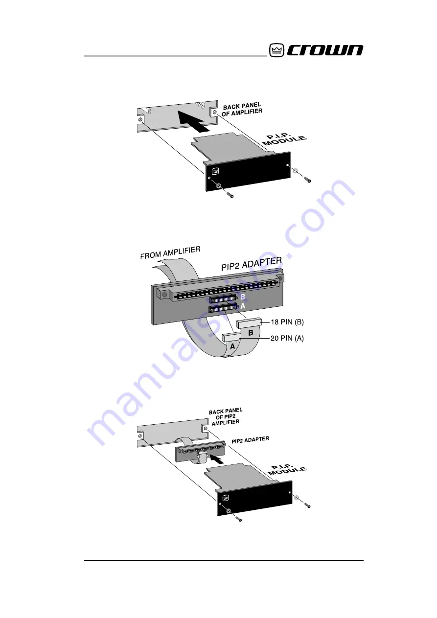
Fig.3.5 PIP2 Input
Adapter Connection
Fig. 3.6 Installation
into a PIP2 Amplifier
Fig. 3.4 Installation into a
Standard PIP Amplifier
All manuals and user guides at all-guides.com
Page 1: ...ce The information provided in this manual was deemed accurate as of the publication date However updates to this information may have occurred To obtain the latest version of this manual please visit...
Page 2: ...des high pass and low pass filters with 18 dB octave 3rd order slopes for bi amp and tri amp systems Five two position sliding switches make it easy for the user to se lect one of twenty four modes of...
Page 3: ...Page 4 P I P XOV Fig 2 1 Front Bottom Views A B S1 S2 S3 S4 S5 B A C C B A D E All manuals and user guides at all guides com...
Page 4: ...the response curve Bessel Butterworth or Chebyshev 2 Facilities A Thumb Screws Use these two thumb screws to fas ten the PIP to the amplifier An E ring prevents them from falling out B Balanced Phone...
Page 5: ...no operation with high pass signal routed to the output con nectors Figure 3 1 shows the switch settings and explanation of each mode The MODE SWITCH SETTINGS FUNCTION S1 S2 S3 S4 S5 CH 1 CH 2 OUTPUT...
Page 6: ...s of the desired val ues Six resistors and six capaci tors are socketed for this purpose Figure 2 1 Three filter types are available Bessel Butterworth and Chebyshev Each differs in its ability to pro...
Page 7: ...ll capacitors should have a 10 tolerance and be of the film type Fig 3 2 Resistor Capacitor Selection Values Where 3 14159 FL Low pass crossover frequency Hz FH High pass crossover frequency Hz R R1 R...
Page 8: ...e of 2 K to 330 K ohms and a value for R6 less than 1 M ohm For this example let C 0 01 mF Then R4 1 2 018 2 x 3 14159 x 400 x 0 01 x 10E 6 19 717 ohms R5 1 8 551 2 x 3 14159 x 400 x 0 01 x 10E 6 4 56...
Page 9: ...in until it is seated against the mounting bracket see Figure 3 4 PIP2 Amplifiers Requires a PIP2 input adapter Crown part number Q43528 1 Connect the PIP2 input adapter to the two input cables of the...
Page 10: ...Page 11 P I P XOV Fig 3 5 PIP2 Input Adapter Connection Fig 3 6 Installation into a PIP2 Amplifier Fig 3 4 Installation into a Standard PIP Amplifier All manuals and user guides at all guides com...
Page 11: ...o a 0 775 V input signal 4 Specifications Signal to Noise Better than 85 dB with 800 Hz low pass or high pass equivalent input noise 20 Hz to 20 kHz Input Impedance Nominally 20 K ohms balanced and 10...
Page 12: ...P XOV 15 100 1 K 4 K 6 dB Fig 4 1 Low Pass Frequency Response 800 Hz Crossover Frequency Fig 4 2 Low Pass Phase Response 800 Hz Crossover Frequency 15 100 1 K 4 K 45 All manuals and user guides at all...
Page 13: ...P XOV 100 1 K 10 K 6 dB 100 1 K 10 K 45 Fig 4 3 High Pass Frequency Response 800 Hz Crossover Frequency Fig 4 4 High Pass Phase Response 800 Hz Crossover Frequency All manuals and user guides at all...
Page 14: ...OUTPUT INPUT CH 2 LOW PASS CH 1 BAND PASS INPUT SIGNAL FLAT OUTPUT FOR DAISY CHAINING MODE 2 OUTPUT INPUT CH 2 BAND PASS CH 1 LOW PASS INPUT SIGNAL FLAT OUTPUT FOR DAISY CHAINING MODE 4 OUTPUT INPUT C...
Page 15: ...PUT INPUT CH 2 BAND PASS CH 1 BAND PASS INPUT SIGNAL FLAT OUTPUT FOR DAISY CHAINING MODE 6 OUTPUT INPUT CH 2 LOW PASS CH 1 LOW PASS INPUT SIGNAL NO OUTPUT MODE 8 OUTPUT INPUT CH 2 HIGH PASS CH 1 HIGH...
Page 16: ...T INPUT CH 2 LOW PASS CH 1 HIGH PASS INPUT SIGNAL NO OUTPUT MODE 10 OUTPUT INPUT CH 2 HIGH PASS CH 1 LOW PASS INPUT SIGNAL NO OUTPUT MODE 12 OUTPUT INPUT CH 2 BAND PASS CH 1 LOW PASS INPUT SIGNAL NO O...
Page 17: ...DE 14 OUTPUT INPUT INPUT SIGNAL FLAT OUTPUT FOR DAISY CHAINING MODE 16 OUTPUT INPUT MONO CH 1 LOW PASS INPUT SIGNAL FLAT OUTPUT FOR DAISY CHAINING MODE 15 CONFIGURE AMPLIFIER IN EITHER BRIDGE MONO OR...
Page 18: ...NO CH 1 HIGH PASS CONFIGURE AMPLIFIER IN EITHER BRIDGE MONO OR PARALLEL MONO MODE OUTPUT INPUT INPUT SIGNAL LOW PASS OUTPUT FOR 2ND AMPLIFIER MODE 18 OUTPUT INPUT MONO CH 1 HIGH PASS INPUT SIGNAL FLAT...
Page 19: ...O CH 1 HIGH PASS CONFIGURE AMPLIFIER IN EITHER BRIDGE MONO OR PARALLEL MONO MODE OUTPUT INPUT INPUT SIGNAL HIGH PASS OUTPUT FOR 2ND AMPLIFIER MODE 22 OUTPUT INPUT MONO CH 1 LOW PASS INPUT SIGNAL BAND...
Page 20: ...BLACK BROWN RED ORANGE YELLOW GREEN BLUE VIOLET GRAY WHITE O 1 2 3 4 5 6 7 8 9 BLACK BROWN RED ORANGE YELLOW 1 10 100 1 000 10 000 GREEN BLUE VIOLET GRAY WHITE 100 000 1 000 000 10 000 000 100 000 000...
Page 21: ...P I P XOV Notes 1 All resistors are in ohms 0 25W 5 unless otherwise specified Schematic All manuals and user guides at all guides com a l l g u i d e s c o m...
Page 22: ...P I P XOV J 0206 3 Schematic 2 All Capacitors are in microfarads unless otherwise specified All manuals and user guides at all guides com...