Operation Manual
I-Tech HD DriveCore Series Power Amplifiers
page 22
I-Tech HD DriveCore Series Power Amplifiers
Operation Manual
page 23
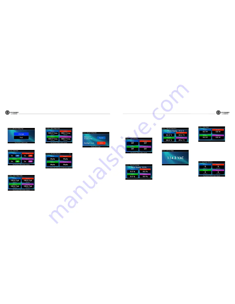
Pink Noise Generator:
Press
Next
and the encoder wheel to select a channel
icon to turn on the generator. Its level will read –100 dB. Adjust the noise level
from –100 dB to +20 dB in 0.5 dB steps by turning the Encoder. To turn off the
generator, select a channel icon or go to another menu item.
LevelMax - RMS Voltage Limiter:
Limits the output rms voltage to an
amount that you set, either OFF or 1 to 500 volts, for each channel. Press the
Encoder to turn on the Limiter. Once it’s on, turn the Encoder to set the voltage.
Front Panel Blackout:
This screen lets you black out the front panel display
unless you press a front-panel button or turn an Encoder. This feature turns
off the LCD backlight and all front panel LEDs except for the fault LEDs and
power-switch green LED. After blackout is enabled, an Encoder press/turn
will “reactivate” the display. If no button is pressed/turned for 5 seconds, the
display will return to blackout mode.
LED Meter Display Type :
Here you can set the LCD bar meters to display
average or peak levels. Turn the Encoder knob to select the option, then press
the knob to confirm your selection.
LevelMax- Peak Voltage Limiter:
Limits the peak output voltage to a level
that you set, either OFF or 1 to 500 volts, for each channel. Press an Encoder to
turn on the Limiter. Once it’s on, turn the Encoder to set the voltage. Additional
controls, such as attack and release, are available through System Architect.
LevelMax - Clip Limiter:
Limits the peak output voltage to just below
clipping for each channel. Press a channel icon to turn it OFF or ON.
7 Advanced Operation
7 Advanced Operation
Load Monitoring:
Press
Next
and the encoder wheel to select a channel
icon to turn speaker load monitoring on or off for a channel. When load
monitoring is on, the load connected to the amplifier output is displayed. The
text below the reported load indicates whether the value is within the limits set
in Sys tem Architect. OFF means load monitoring is off. LOW means the load is
below limits. HIGH means the load is above limits. NORMAL means the load is
within limits. (Output must be sufficient)
Thermal %:
This indicates the amplifier temperature in percent, where 100%
is the maximum allowable temperature. If Thermal % reaches 100%, the
amplifier is out of thermal headroom and has shut down (or will very soon).
Measurements are shown for Channel 1, Channel 2, Channel 3, Channel 4,
and PSU.
Thermal Temp deg. C:
This screen displays the temperature in degrees
Celsius of the Ch. 1 output devices, Ch. 2 output devices, Ch. 3 output
devices, Ch. 4 output, and the power supply.
7.2.2 MONITOR MENU
This menu lets you monitor the status of the amplifier.
AC Voltage:
This shows the AC line voltage at the AC cord inlet to the
amplifier.
Operating Time:
This displays the number of hours the amplifier has been
on since manufacture. Like a car’s odometer, it shows the total amount of
operating hours and cannot be reset. All I-Tech HD amplifiers come with a
variable amount of operating time on them due to burn-in and testing before
shipping.
Watts Output:
This displays the slow-averaged continuous output power of
each channel in watts.
7.2.3 ALERT MENU
This menu displays a wide variety of errors in the signal, amplifier, or load.
Amp Output Clip Errors:
A
clip error
occurs if the number of clip events in
the amplifier output exceeds the value set with the
Count slider
(within the
time set by the Time slider) on the Amplifier Settings page in System Architect.
When an error occurs, the count displayed in this screen is incremented, and
the operat ing time since the error is displayed.
To clear this screen, select a channel icon.


