I-Tech HD Series
Power Amplifiers
I-Tech HD Series
Power Amplifiers
page 20
page 21
Operation Manual
Operation Manual
Network Troubleshooter
The network troubleshooter can assist you in setting up your HiQnet network for the first time. Using the
troubleshooter, you can address your components and be informed of addressing and other errors in the system.
Please note that this wizard is designed to work with devices that are on the same physical network segment as
the computer it is running on. It will not work through a router.
Select Network Card
The first page of the wizard lists all the network adapters currently in the computer. If you have more than one
adapter, you can scroll through the list and see the
IP Address
assigned to each card.
If you have a card with an IP address of 0.0.0.0, it typically means one of several things:
1.
The card is disabled.
2.
The card is not connected to a network.
3.
The card is setup to obtain its address from a DHCP server, and no DHCP server is available.
Select the card that is connected to the HiQnet system and click the
Next
button. The Wizard will walk you
through the rest of the process. Please see the System Architect online help for more information.
Software-Controllable Onboard DSP
Crown’s latest-generation Digital Signal Processing is built into the I-Tech HD amplifier. Its 24-bit/96kHz
converters offer extremely low noise and extended dynamic range. When you use an I-Tech HD amp, the
loud speaker processors, crossovers, limiters and delays are in the onboard DSP – so you don’t need those rack-
mounted devices. This drastically cuts setup time, commissioning, rack space and costs.
The I-Tech HD’s DSP can be monitored and controlled with a computer running System Architect software, and
connected to the amplifier Network Connector by a network Category 5 cable.
Some applications for this DSP are:
•
Set up signal flow
•
Optimize system gain structure
•
Set up speaker configurations (set the drive levels, frequency bands, delays and limiting for
your particular speakers)
•
Set up EQ, filtering, compression, and much more.
Maximum analog
input
Low +21 dBu (0 dB)
High +15 dBu (+6 dB)
Analog
input
AES
input
Cobranet
input
Analog
input
sensitivity
Source
select
AES input trim
Cobranet input trim
Output
attenuator
Fixed
gain
compensation
Limiters
Amplifier
Low +21 26/32 dB
Hi +15 32/38 dB
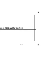
Fixed gain
Fixed-Gain mode in the I-Tech HD
Fixed-gain mode makes any I-Tech HD model have the same gain, regardless of output power.
To do that, fixed-gain mode sets the
Analog Input Sensitivity
to 0 dB gain, then adjusts the
Fixed Gain
Compensation
fader, and the
Maximum Analog Input
, to achieve 26 or 32 dB of gain (if the Maximum
Analog Input is set Low), or to achieve 32 or 38 dB of gain (if the Maximum Analog Input is set High), no matter
what model the amplifier is.
However, In fixed-gain mode, the input trims (Analog, AES, CobraNet) can still be adjusted.
Summary of Contents for I-T9000 HD
Page 21: ......