


10
}
CMA-1
3
4
5
1
3
4
5
SPEAKER
OUTPUTS
REMOTE
INPUTS
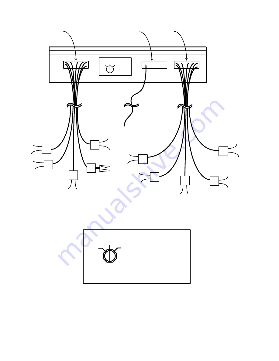
Fig. 7 4-Channel Connections
Fig. 8 Switch Position for 4 CH Operation
1
2
4
3
WHITE
CABLES
To CH1
Source
(Left Front)
To CH2
Source
(Right Front)
To CH3
Source
(Left Rear)
Not
Connected
use wire
nut
To CH5
Source
(Right Rear)
BLK/WHT
CH1+
BLK
CH1-
5
2
WHT/RED
CH2+
WHT
CH2-
RED/WHT
CH3+
RED
N/C
Cut and
Tape
GRN/YEL
CH3-
YEL/RED
CH4-
BLU/RED
CH4+
}
CMA-1
3
4
5
CAUTION
: Read instruction manual before
operating this switch. Improper installation
could damage vehicle and amplifier.
GRN
N/C
Cut and
Tape


