


Page 25
Contractor Series Power Amplifiers
Reference Manual
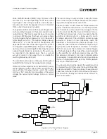
Pulse Width Modulated (PWM) string of pulses at 250
kHz that vary in width depending on the level of the
input signal. These strings of pulses, one for the posi-
tive side and one for the negative side, are connected
to the output stage via optocouplers.
The signals from the optos are then passed to gate driv-
ers that amplify the pulses to the level required to drive
output devices. The driven output devices are now able
to produce PWM pulses that have an output voltage
from the negative high-voltage rail (–Vcc) to the positive
high-voltage rail (+Vcc). This output voltage is always
the same (2 * Vcc) but the width of the pulses is still
dependent on the level of the input signal. The positive
and negative output PWM pulses then pass through in-
ductors and are summed together. Summing the output
signals through inductors reconstructs the audio sig-
nal, amplified to the desired level. There is a small
amount of ripple on the output that is at double the
switching frequency (500 kHz).
The amplified audio signal is then passed through an
output filter that removes the residual ripple voltage.
Protection for the output devices is performed by a very
precise pulse-by-pulse current limiter circuit that oper-
ates each time the output devices switch. The current
limiting is “flat” meaning that, regardless of the output
voltage, the output current always limits at a certain
value.
The turn-on delay circuitry functions to keep the modu-
lators turned off (which keeps the outputs from switch-
ing) until all supplies are up and stable.
Thermal probes monitor Heatsink temperatures and
power transformer temperature. As the temperatures
rise, the probes send a proportional voltage to the fan
control circuit and the Thermal Limit Control (TLC) cir-
cuit. The fan normally runs at very low speed when the
amplifier is idling or when it is being used for low to
moderate duty work. If the amplifier is delivering large
amounts of power into low impedance loads, the
heatsinks or transformer may heat up enough to in-
crease the speed of the fan to medium and possibly to
high speed. If the temperature continues to increase,
the TLC circuit uses the compressor to reduce the gain
of the input stage and thus reduce the power dissipated
by the amplifier. As a further protective measure, if the
temperature continues to rise (due to blocked airflow
for example), the amplifier will stop running and keep
the fan on high speed to quickly bring the temperature
back to an operational level.
If a signal presented at the input of the amplifier will not
be passed through to the output, the Fault LED will blink
to get your attention. The turn-on delay, for example, will
cause each channel’s LED to blink because the ampli-
fier remains in standby for a few seconds before it al-
lows audio output.
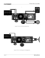
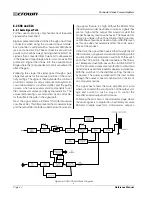
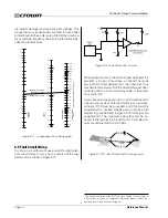
Figure 6.4 CL4 Circuit Block Diagram


