background image

]


Balanced Current Amplifier

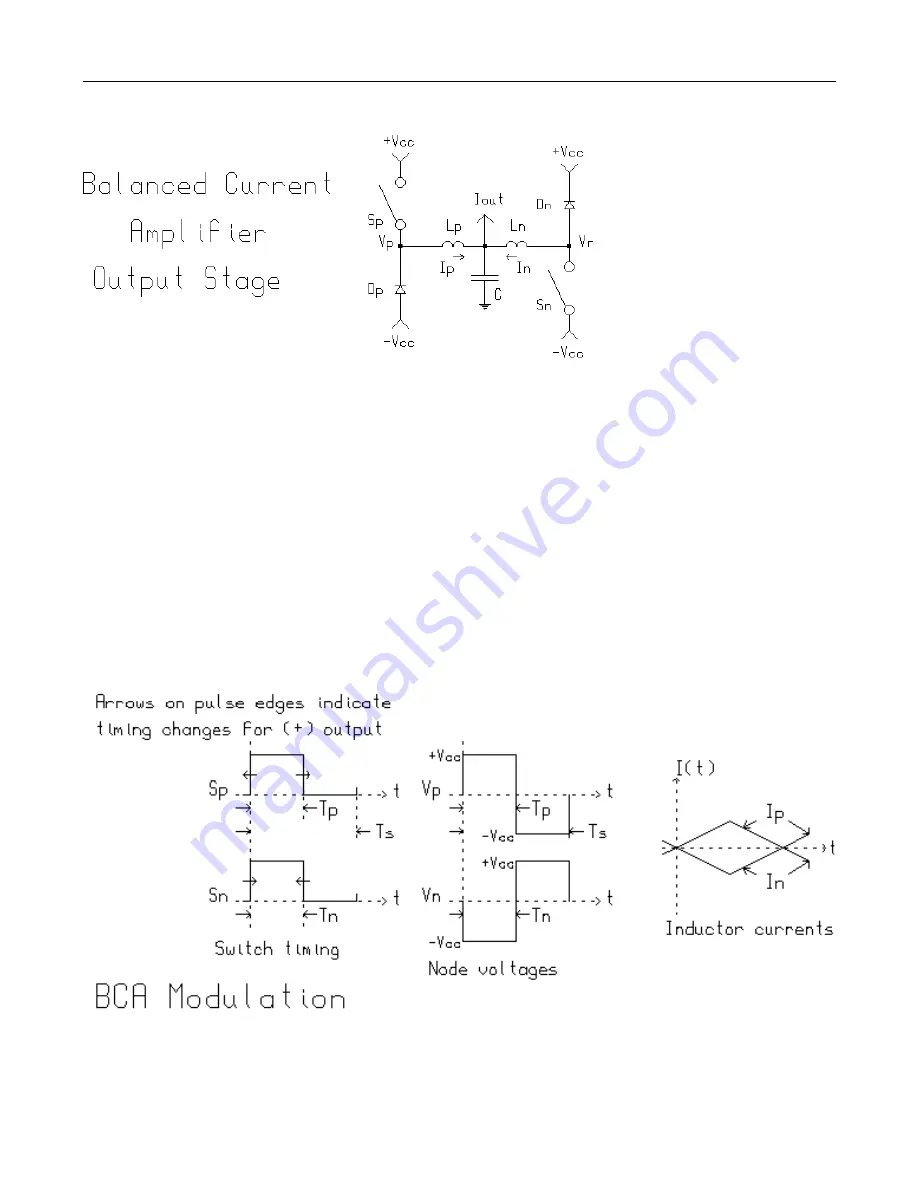
cycle). When the Sp and Sn switches are both closed
during interval Tp (or Tn) the main output inductor cur-
rent magnitudes increase at a rate of Vcc/L where
L=Lp=Ln. When the switches are both off during the in-
terval following Tp (equal to Tp=Ts-Tp), the inductor volt-
age is reversed and the output currents ramp down at
the same magnitude. Ip and In are of equal magnitude
but of opposite polarity, thus the output currents are said
to be balanced and therefore the name Balanced Cur-
rent Amplifier or BCA.

The converter is always biased
such that current continuously
flows in the output inductors which
means that either a FET (Sp or Sn)
or its companion free-wheeling di-
ode (Dp or Dn) are conducting. The
converter is said (in power conver-
sion jargon) to be operating in CCM
(continuous current mode). As
such the Vp and Vn nodes are ei-
ther at the +Vcc or -Vcc potential.

There is an equivalent circuit that
can enlighten one’s understanding
of the circuit’s operation. There are
four state permutations of the
MOSFET switches that can exist.
Two are states with one FET on, one

with no FETs on and one with both FETs on. The equiva-
lent circuit is composed of a three position switch which
can either Vcc, ground or -Vcc to an output in-
ductor of value L/2 where L=Lp=Ln. This equivalent cir-
cuit will be switched to ground whenever both Sp and
Sn switches are in the same state (on or off). If only one
of the Sp and Sn switches is on, the equivalent circuit
switch will be set to the supply polarity of the Sp or Sn
switch which is on.

4

Summary of Contents for BCA

Page 1: ...produce the other polarity of output current he would turn on the other tube Previously with class A designs both tubes were always turned on and even at no signal were dissipating large amounts of quiescent power By careful selection of the class B bias point he was able to produce essentially undistorted output without hav ing a massive quiescent power loss This greatly in creased the power outp...

Page 2: ...tive energy returned from the load to the amplifier is reabsorbed and reoutput with little loss Non switching amplifiers are forced to dissipate all of the returned energy plus much more the latter ratio is a function of the topology used and is typically three fold or more Difficult loads are driven with grace and ease Current overload is smooth and sonically identical to voltage overload Thermal...

Page 3: ...to include both the push pull concept and the notion of strict time alterna tion of the active devices used to effect the push pull power stage Push pull operation is possible with the output of a power stage being a signal statistic and not an expression of the immediate state of the power devices used to create the signal statistic Such is the case within the Crown BCA power stage Note that push...

Page 4: ...n free wheeling di ode Dp or Dn are conducting The converter is said in power conver sion jargon to be operating in CCM continuous current mode As such the Vp and Vn nodes are ei ther at the Vcc or Vcc potential There is an equivalent circuit that can enlighten one s understanding of the circuit s operation There are four state permutations of the MOSFET switches that can exist Two are states with...

Page 5: ...current occurs at zero output the very state which is most commonly occupied by audio and many other signals The effective output frequency is doubled with out operating any switch at double frequency Bridged output circuits are commonly understood to double the ripple frequency but note that they use four switches to obtain a doubling of frequency When the BCA s output stages are used in a full b...

Page 6: ...s are increasing propor tional to the number of switches This re duces the amount of low pass filtering re quired to eliminate the switching signal from the output Since ripple currents simultaneously increase in frequency while decreasing in am plitude the filtering re quirements are multiply relaxed Note that no matter how many balanced current power stages are inter leaved total ripple re jecti...

Page 7: ...e of being a full four quadrant power converter Much more could be said however it is not the intent of this document to be a textbook on state of the art amplifier design GRS 12 20 96 Negative Programmed Output The modulator for the basic Crown BCA power stage is simpler than one might at first imagine Having twice the standard amount of resultant information it has two high speed comparators dri...

Reviews: