18
English
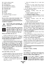
20
Vertical emitter window
21
Battery (AA-type) *
22
Carrying bag *
23
Horizontal emitter window
24
Laser beams on / off switch
25
Mounting screw *
26
Locking handle *
27
Carriage *
28
Magnet *
29
Tripod *
30
Charger indicator *
31
Socket for charger connection *
* Optional extra
Not all of the accessories illustrated or de-
scribed are included as standard delivery.
Installation / regulation
Do not draw up the fastening ele-
ments too tight to avoid damaging
the thread.
Mounting / dismantling / adjustment
of some elements is similar for all
appliance models. In this case no
particular appliance model is indi-
cated in the explanatory drawing.
Battery installation (see fig. 1-2)
•
Install the batteries
21
(AA-type, 4 pcs�) in
the housing
14
, as shown onto fig. 1.
Caution:
during installation of batteries 21 in the hous-
ing 14, observe correct polarity (see fig. 1).
•
Open cover
8
(see fig. 2.1).
•
Install housing
14
(with installed batteries
21
)
or battery
13
into appliance (see fig. 2.2).
Note:
the housing 14 and battery 13 are specially
shaped and can only be installed in one posi-
tion. Do not use excessive force when install-
ing the housing 14 or battery 13 to avoid dam-
aging them or appliance.
•
Close cover
8
(see fig. 2.3).
•
Disassemble in the reverse sequence�
Universal holder (see fig. 3-8)
•
Install the appliance on the universal holder
18
using the mounting screw
25
as shown in fig. 3-4.
•
You can move the appliance mounted on the
universal holder
18
up or d
own (see fig. 5).
•
Rotate the locking handle
26
as shown
onto fig. 5.1 - this will allow to move the car
-
riage
27
up or down�
•
Move the carriage
27
up or down (see
fig. 5.2).
•
Rotate the locking handle
26
as shown
onto fig. 5.1 - this will lock the position of the
carriage
27
�
•
You can rotate the appliance mounted on the
universal holder
18
(see fig. 6).
•
Release mounting screw
25
(see
fig. 3.2, 4.2).
•
Rotate the appliance (see fig. 6.1).
•
Tighten mounting screw
25
�
•
For
CT44059, CT44060, CT44065
- you can
move horizontally the appliance mounted on the
universal holder
18
�
•
Release mounting screw
25
(see
fig. 3.2, 4.2).
•
Move the appliance (see fig. 6.2).
•
Tighten mounting screw
25
�
•
You can install the universal holder
18
on fer-
romagnetic metal surfaces (elements of metal
structures, metal doors, frame structures for fix
-
ing drywall, etc�) using the magnets
28
� In this
case, the appliance shall be installed in the posi-
tion shown in figure 7.
Note: if you flip the ap
-
pliance, the self-leveling system of the laser
head will be misguided.
•
You can suspend the universal holder
18
as
shown in figure 8.1.
•
You can install the universal holder
18
on a
tripod
29
with a mounting thread 1/4"-20 UNC
or 5/8"-11 UNC (see fig. 8.2).
Attention: tri-
pod 29 is not included in delivery set.
•
If you hear an sound signal when the ap-
pliance is turned on and the laser beams are
flashing, the deviation of the appliance from the
horizontal plane is more than ±3°� In this case,
try changing the position of the appliance or re-
install it�
Battery charging
[CT44060, CT44061, CT44065]
Initial operating
The appliance is delivered with partial bat-
tery 13 charge. Fully charge the battery 13
before the first use of the appliance.
If the power indicator 7 flashes
when the appliance is switched on,
it means that the battery 13 is dis-
charged and needs to be charged.
Summary of Contents for 7640186242332
Page 1: ......
Page 3: ...3...
Page 4: ...4...
Page 5: ...5...
Page 6: ...6...
Page 7: ...7...
Page 8: ...8...
Page 9: ...9...
Page 10: ...10...
Page 11: ...11...
Page 12: ...12...
Page 13: ...13...
Page 14: ...14...
Page 31: ...31...
Page 36: ...36 www crown tools com...
Page 39: ...39 CT44059 CT44060 CT44065 360...
Page 46: ...46 CT44059 CT44060 CT44065 360 1...
Page 51: ...51...
Page 52: ...52...
Page 53: ...53...
Page 54: ...54...
Page 55: ...55...
Page 56: ...56...
Page 57: ...57...
Page 58: ...58...
Page 59: ...59...
Page 60: ...60...
Page 61: ...61...
Page 62: ...62...
Page 63: ...63...
Page 64: ......


