


MPR/MIB User’s Manual
Wireless Sensor Networks
Doc. # 7430-0021-06 Rev. A
Page 16
b
= 0.000214381
c
= 0.000000093
R
1
= 10 k?
ADC_FS
= 1023
ADC
= output value from the Mote’s ADC measurement.
4.3
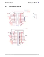
Block Diagram and Schematics for the MPR500/510/520 MICA2DOT
Feature
Chapter
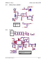
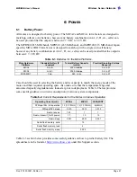
Battery / Ext. Power
6
Radio
7
Antenna
8
Data Flash Logger
9
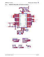
Atmega128
10
Expansion Connector
11
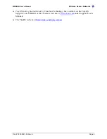
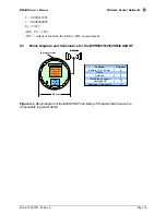
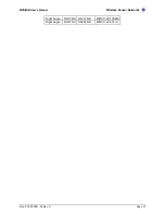
Figure 4-1.
Block diagram of the MICA2DOT and listing of Chapters that discuss the
components in greater detail.
ATMega128L
µ
controller
Analog I/O
Digital I/O
Freq.
Tunable
Radio
Logger Flash
Antenna
Antenna
25 mm
19 peripheral pins


