Cross Technologies 2016-25-01 Instruction Manual Download Page 18

Appendix

ETHERNET Interface Installation and Operation

1.0 General Information

The Cross Technologies frequency converter is equipped with a 10/100 Base-T compatible Ethernet interface 
for control and monitoring of its operating parameters.  An HTML script interface allows the user to monitor 
and control the converter using a standard web browser.  SNMP (Simple Network Management Protocol) is 
also supported.  Contact Cross Technologies for the SNMP MIB file.  

1.1  Methods of Connection

1.1.1


Directly Connected to a PC:

For control from a local PC, attach the frequency converter’s Ethernet port to the Ethernet network connector 

on the PC using a crossover RJ-45 cable.  

1.1.2 LAN Connection 

For LAN connections, attach the frequency converter’s Ethernet port to the LAN using a normal RJ-45 cable.  

Use any PC on the LAN to connect to the frequency converter.

1.2  Ethernet Configuration

Each frequency converter must be configured with an appropriate IP address, Netmask, and Gateway assigned 
by your network manager.  The frequency converter is set at the factory with a static address that is written on 
a tag attached to the unit.  The device server in the frequency converter has a built in HTTP based configuration 
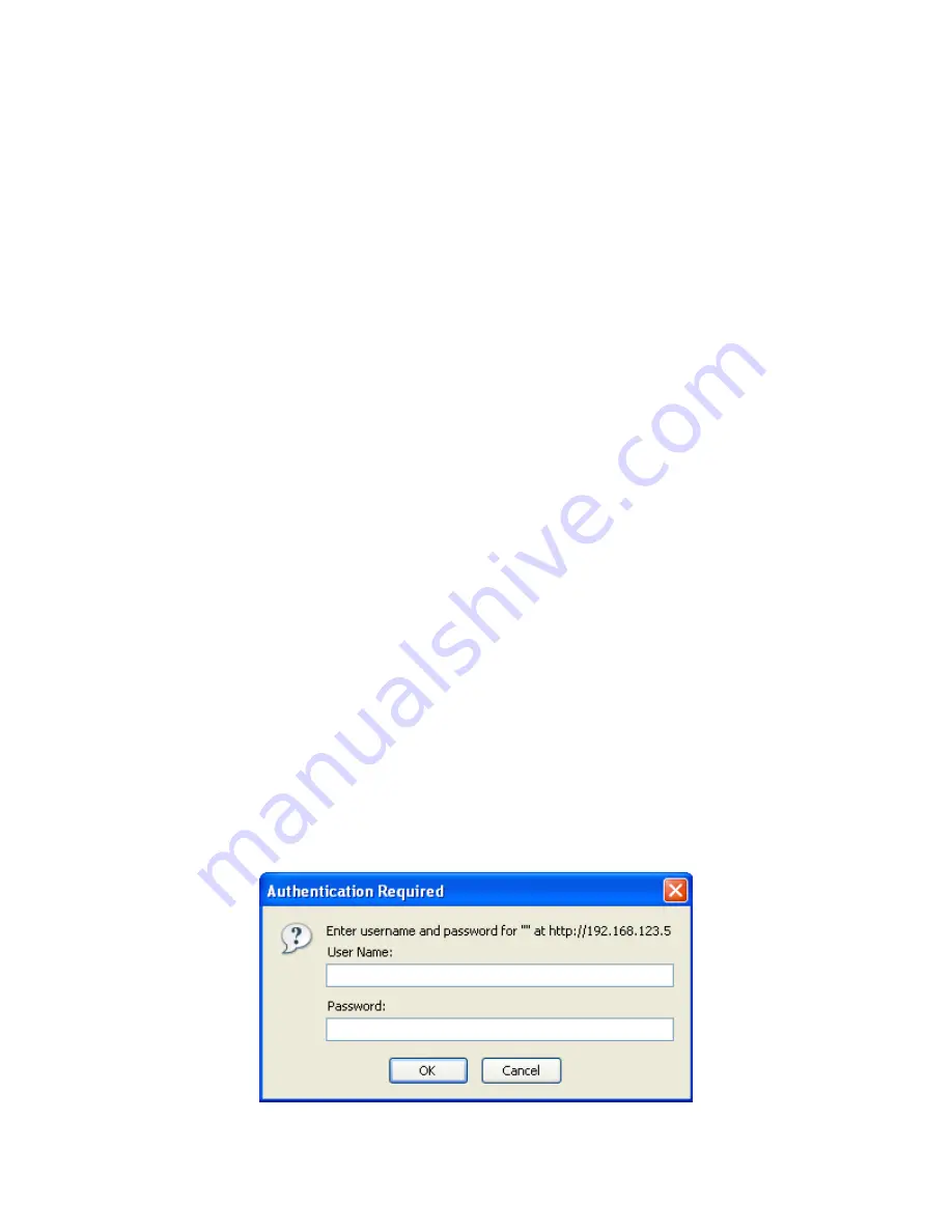
manager that is used to configure network settings.  To access the configuration manager open a web browser 
and enter the IP address of the frequency converter in the browser's address field.   The window shown in 
Figure 1-A will appear.  As delivered, there is no password set.  Choose your user name and password here 
or leave those fields blank and click OK to proceed to the configuration manager webpage.

2016-25-01 Manual _Rev A


     Page 18

                               3/26/09

Summary of Contents for 2016-25-01

Page 1: ...ies Inc but may be reproduced or duplicated without the prior permission of Cross Technologies Inc for purposes of operating the equipment When ordering parts from Cross Technologies Inc be sure to in...

Page 2: ...a period of one year after shipment to customer Cross Technologies Inc s obligation under this warranty is limited to repairing or at Cross Technologies Inc s option replacing parts subassemblies or...

Page 3: ...ar on the LCD display Connectors are N type for RF In BNC for IF Out 10 MHz In 10 MHz Out and IF Monitor SMA for RF Monitor and 1st LO Monitor The unit is powered by a 100 240 10 VAC power supply and...

Page 4: ...kHz 1kHz 100 Hz dBC Hz Phase Noise Freq Controls Indicators Frequency Selection Direct readout LCD manual or remote selection Gain Selection Direct readout LCD manual or remote selection Power Alarm R...

Page 5: ...7 8 9 Female DB 9 PC Com Port Male DB 9 2015 16 17 M C Port M C Cable Diagram Cross Technologies Frequency Converters RX RX TX TX DTR SG DSR RTS CTS SG Connector Rear panel DB 9 male J10 Pinouts Pinou...

Page 6: ...tus Requests Command Syntax Description Command Status aaS1 Returns aaS1bbbbbbbccde where bbbbbbb Rx frequency cc Rx gain d 0 non inverted Receiver 1 inverted e 0 Summary Alarm 1 Alarmed 0 Normal 10MH...

Page 7: ...should be used ONLY when RS 485 OPTION Q is selected Table 1 2 2016 25 01 Comm mands Commands Command Syntax Description Set Receiver Frequency aaC2xxxx where xxxxxxx 7 characters Range 200000 to 2500...

Page 8: ...quipment is not compromised Additional space between unit may be required E Circuit Overloading Consideration should be given to the connection of the equipment to the supply circuit and the effect th...

Page 9: ...inch deep chassis A switching 12 24 5 VDC power supply provides power for the assemblies The 2016 25 01 can be secured to a rack using the 4 holes on the front panel Figure 2 1 shows how the 2016 25...

Page 10: ...2 RF IN 2000 2500 MHz 70 to 20 dBm input 50 BNC female see Table 2 2 for other options J20 ETHERNET CONNECTION RJ45 Ethernet Connector 1st LO MONITOR Sample of the 1st LO of the downconverter FIGURE 2...

Page 11: ...ock to an external reference and automatically switch to the internal reference if both PLL circuits become unlocked Once the converter switches to the internal reference it will remain there until th...

Page 12: ...nd the input level provided See Section 2 5 Menu Settings 6 Be sure DS6 green DC Power is on and DS2 red Alarm is off Figure 2 3 7 AC Fuse The fuse is a 5 mm X 20 mm 2 amp slow blow Type T and is inse...

Page 13: ...ect RS232 RS422 RS 485 or Ethernet option W85 Remote Operation option Q Menu 8 Select Remote Address for Unit RS485 only option Q Save Menu When R is selected in any above menu or the next menu item a...

Page 14: ...may desire 2 6 3 Control Switches 1 Menu Execute Any change to the programming of the unit must be initiated by pressing the Menu Execute switch and completed by pressing the Menu Execute switch 2 Hor...

Page 15: ...quency F 2250 R Pressing the Up Down switch down will toggle the display to F 2350 R By using the horizontal rocker switch the cursor can be moved left or right F 2350 R NOTE CHANGES DO NOT TAKE PLACE...

Page 16: ...en push the Menu Execute switch to get to the Gain setting G 00 R Press the Up Down switch to change the gain in 1 or 10 dB steps G 10 R By using the horizontal rocker switch the cursor can be moved l...

Page 17: ...own Gain 0 to 50 Menu 3 Set Unit to Remote Operation Menu 4 Select Non inverting or Inverting Spectrum Menu 5 Select External 10 MHz Reference option E Menu 6 Select 10MHz Output option E Menu 7 Selec...

Page 18: ...cy converter s Ethernet port to the LAN using a normal RJ 45 cable Use any PC on the LAN to connect to the frequency converter 1 2 Ethernet Configuration Each frequency converter must be configured wi...

Page 19: ...r the IP address Subnet mask and Gateway address with delimiter dots example 192 168 192 47 1 3 Webpage M C Enter the following address in a web browser to access the M C webpage http ip address seria...

Page 20: ...stablish such a Telnet connection using Windows XP s Hyper Terminal utility Start the Hyper Terminal application and select New Connection from the File drop down menu The next screen is a Connect To...

Page 21: ...write strings After setting your desired community strings you will be prompted to Enter IP addresses for SNMP traps You must enter at least one and up to four IP addresses of SNMP managers that will...

Page 22: ...Figure 2 F Device Server Configuration Menu 2016 25 01 Manual _Rev A Page 22 3 26 09...

Page 23: ...INC 6170 Shiloh Road Alpharetta Georgia 30005 770 886 8005 FAX 770 886 7964 Toll Free 888 900 5588 WEB www crosstechnologies com E MAIL info crosstechnologies com Printed in USA 2016 25 01 Manual _Rev...

Reviews: