background image

1.2  Technical Characteristics

1584-45 Manual, Rev C

          Page 4


           4/24/13


SiDACTOR


Surge Suppressor


> 18 dB min., 20 dB typical


Port to Port Isolation


300 ma, maximum 


Output LNB Current


Green LED indicates DC Voltage prior to diode OR


Power


12 dB min., 14 dB typical


Return Loss


Options

 Other


Indicators


In-Band Characteristics


Output Characteristics


Input Characteristics


50

Ω

, BNC RF Connectors


-D


19 inch Standard Chassis, 1.75” High x 12” Deep


± 1.0 dB, 950 - 2150 MHz;  ± 0.5 dB, any 20 MHz increment


Frequency Response


> 35 dB min., 40 dB typical


Coupler to Coupler Iso’n


0 dB ± 1.0 dB


Gain


75

Ω

, (50

Ω

, Option -D)


Impedance 


-20 dBm total maximum


Input Level


12 dB min., 14 dB typical


Return Loss


75

Ω

, (50

Ω

, Option -D)


Input Impedance

 TABLE 1.0

 1584-45 RF Splitter Equipment Specifications**


75

Ω

, BNC RF Connectors


-B


Redundant Switching Power Supplies, 

 100-240 ±10% VAC, 50 - 60 Hz, 30 watts maximum.
 NOTE: Model 1584-45S has a single non-redundant, switching power
 supply and does not provide the LNB Power Insertion Feature.


AC Power 


Type F, female


RF Connectors


22 ± 2 VDC


LNB DC Voltage 


*10˚C to 40˚C; Specifications subject to change without notice.                                                                  © Cross Technologies, Inc.


Mechanical 


Green LED indicates LNB Power Insertion on splitter input (J-17)


LNB DC Voltage

Summary of Contents for 1584-45

Page 1: ...are proprietary to Cross Technologies Inc but may be reproduced or duplicated without the prior permission of Cross Technologies Inc for purposes of operating the equipment When ordering parts from C...

Page 2: ...s Technologies Inc s obligation under this warranty is limited to repairing or at Cross Technologies Inc s option replacing parts subassemblies or entire assemblies Cross Technologies Inc shall not be...

Page 3: ...puts are AC coupled so no DC appears on their center conductors On the front panel green LEDs indicate presence of 22 VDC at each LNB power supply output and DC voltage test points allow monitoring th...

Page 4: ...B min 40 dB typical Coupler to Coupler Iso n 0 dB 1 0 dB Gain 75 50 Option D Impedance 20 dBm total maximum Input Level 12 dB min 14 dB typical Return Loss 75 50 Option D Input Impedance TABLE 1 0 158...

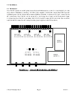
Page 5: ...e front panel Figure 2 1 shows how the 1584 45 is assembled J28 J27 J26 and J25 connect DC Power to the fuses as shown and J30 and J29 connect the DC voltage from the power supplies to the PCB as show...

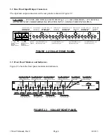
Page 6: ...0 240 10 VAC 47 60 HZ Uses 2 amp Fast Blo 5mm fuse FIGURE 2 2 1584 45 REAR PANEL 2 3 Front Panel Monitors and Indicators Figure 2 3 shows the front panel monitors and indicators GROUND TEST POINT LNB...

Page 7: ...stalled in the rear panel fuse holders to insure proper signals and voltages NOTE FOR OPTIMUM PERFORMANCE THE MONITOR PORT AND SPLITTER PORTS SHOULD BE TERMINATED WITH 75 OHM TYPE F TERMINATIONS WHEN...

Page 8: ...e equipment is not compromised Additional space between unit may be required E Circuit Overloading Consideration should be given to the connection of the equipment to the supply circuit and the effect...

Page 9: ...HNOLOGIES INC 6170 Shiloh Road Alpharetta Georgia 30005 770 886 8005 FAX 770 886 7964 Toll Free 888 900 5588 WEB www crosstechnologies com E MAIL info crosstechnologies com 1584 45 Manual Rev C Page 9...

Reviews: