Cross Technologies 1584-116 Instruction Manual Download Page 5

2.0  Installation

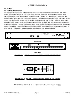
2.1  Mechanical - The 1584-116/116S consists of one RF printed circuit board (PCB) housed in a 1 RU (1.75 
inch high) by 12 inch deep chassis. Redundant, switching, +24 VDC power supplies with the DC output diode 
OR’d provide redundant power for the internal and external amplifiers and LEDs. (Model 1584-116S has a 
single non-redundant, switching power supply). Connectors are type F, female for the RF connections (BNC, 
female option -B or -D). The 1584-116/116S can be secured to a rack using the 4 holes on the front panel.  
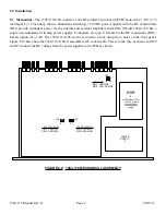
Figure 2.0 shows how the 1584-116/116S is assembled. J25 connects DC Power to the fuse as shown and J30 
and J29 connect the DC voltage from the power supplies to the PCB as shown.

POWER 

SUPPLY

A

2  1 

J29

+24 PS IN (AC A)
PIN 1, +24 VDC
PIN 2, GROUND

POWER 

SUPPLY

B

NOTE:Model 1584-

116S has a single 

non-redundant, 

switching power 

supply

J30

+24 PS IN (AC B)
PIN 1, +24 VDC
PIN 2, GROUND

J25

LNB FUSE
PIN 1, LNB SIDE
PIN 2, +22 VDC SIDE

2  1 

1

2

FIGURE 2.0   1584-116 MECHANICAL ASSEMBLY

1584-116 Manual Rev. G


          Page 5


                    04/23/13

Summary of Contents for 1584-116

Page 1: ...oduced or duplicated without the prior permission of Cross Technologies Inc for purposes of operating the equipment When ordering parts from Cross Technologies Inc be sure to include the equipment mod...

Page 2: ...oss Technologies Inc s obligation under this warranty is limited to repairing or at Cross Technologies Inc s option replacing parts subassemblies or entire assemblies Cross Technologies Inc shall not...

Page 3: ...ont panel two green LED s indicate the presence of DC voltage from each of the two power supplies and another green LED indicates LNB power insertion Two test points are also provided on the front pan...

Page 4: ...amplifiers LNB DC Voltage Green LED indicates LNB power insertion on splitter input J17 Other LNB DC voltage 22 2 VDC Output LNB current 300 ma max Surge Suppressor SiDACTOR RF connectors Type F fema...

Page 5: ...ons BNC female option B or D The 1584 116 116S can be secured to a rack using the 4 holes on the front panel Figure 2 0 shows how the 1584 116 116S is assembled J25 connects DC Power to the fuse as sh...

Page 6: ...LITTER J8 J7 J6 J5 J4 J3 J2 J1 SPLITTER OUTPUTS Type F female 75 Terminate when not used See Table 2 0 for other connector options FIGURE 2 1 1584 116 REAR PANEL TABLE 2 0 R RF 2 0 RF Connector Option...

Page 7: ...FUSE F1 HOLDER 22 VDC WILL APPEAR ON THE SPLITTER INPUT CONNECTOR J17 CENTER PIN NOTE FOR OPTIMUM PERFORMANCE THE SPLITTER PORTS SHOULD BE TERMINATED WITH 75 OHM TYPE F TERMINATION WHEN NOT USED AC F...

Page 8: ...equipment is not compromised Additional space between unit may be required E Circuit Overloading Consideration should be given to the connection of the equipment to the supply circuit and the effect...

Page 9: ...S INC 6170 Shiloh Road Alpharetta Georgia 30005 770 886 8005 FAX 770 886 7964 Toll Free 888 900 5588 WEB www crosstechnologies com E MAIL info crosstechnologies com Printed in USA 1584 116 Manual Rev...

Reviews: