background image

H.

FILTER (ROLLING AVERAGE) COMMANDS

T h e s e   c o m m a n d s   a r e   u s e d   t o   c o n t r o l   t h e   F i l t e r   f u n c t i o n .    

SENSe:AVERage:STATe <ON|OFF> or <1|0>

E n a b l e s   o r   d i s a b l e s   t h e   f i l t e r   ( r o l l i n g   a v e r a g e )   f u n c t i o n .  

SENSe:AVERage:STATe? 

R e t u r n s   “ 0 ”   ( O F F )   o r   “ 1 ”   ( O N ) .  

SENSe:AVERage:COUNt <

N o .   o f   r e a d i n g s >

S e t s   t h e   n u m b e r   o f   r e a d i n g s   t o   b e   f i l t e r e d   o r   a v e r a g e d   ( 2     5 0 ) .  

SENSe:AVERage:COUNt? 

R e t u r n s   t h e   n u m b e r   o f   r e a d i n g s   t o   b e   f i l t e r e d   ( a v e r a g e d ) .  

S e l e c t i n g   t h e   F i l t e r   w i l l   a u t o m a t i c a l l y   d e s e l e c t   t h e   S e t t l i n g   A l g o r i t h m .

I.

SETTLING ALGORITHM COMMANDS

T h e s e   c o m m a n d s   a r e   u s e d   t o   c o n t r o l   t h e   S e t t l i n g   A l g o r i t h m .    

SENSe:SETTling:STATe <ON|OFF> or <1|0> 

E n a b l e s   o r   d i s a b l e s   t h e   S e t t l i n g   f u n c t i o n .  

SENSe:SETTling:STATe? 

R e t u r n s   “ 0 ”   ( O F F )   o r   “ 1 ”   ( O N ) .  

SENSe:SETTling:COUNt <

N o .   o f   r e a d i n g s >

S e t s   t h e   m a x i m u m   n u m b e r   o f   r e a d i n g s   t o   b e   t a k e n   ( 2     9 9 9 ) .  

SENSe:SETTling:COUNt? 

R e t u r n s   t h e   m a x i m u m   n u m b e r   o f   r e a d i n g s   s e l e c t e d .  

SENSe:SETTling:LIMit <

N o .   o f   d i g i t s >

S e t s   t h e   m a x i m u m   n u m b e r   o f   d i s p l a y   d i g i t s   ( 1     9 9 9 )   b y   w h i c h   t w o   c o n s e c u t i v e  
r e a d i n g s   m a y   d i f f e r ,   f o r   t h e   m e a s u r e m e n t   t o   b e   d e f i n e d   a s   ‘ s e t t l e d ’ .  

SENSe:SETTling:LIMit? 

R e t u r n s   t h e   m a x i m u m   n u m b e r   o f   d i s p l a y   d i g i t s   s e l e c t e d .  

S e l e c t i n g   t h e   S e t t l i n g   A l g o r i t h m   w i l l :  

D e s e l e c t   t h e   F i l t e r   f u n c t i o n .  
C h a n g e   A v e r a g e   ( A V E )   C u r r e n t   m o d e   t o   P o s i t i v e   ( + I )   C u r r e n t   m o d e .  

S e l e c t i n g   F i l t e r   o n   w i l l   a u t o m a t i c a l l y   d e s e l e c t   t h e   S e t t l i n g   A l g o r i t h m .  
I f   t h e   S e t t l i n g   A l g o r i t h m   i s   o n ,   A v e r a g e   ( A V E )   c u r r e n t   c a n n o t   b e   s e l e c t e d .

Operating Instructions

Digital Microhmmeter Type DO7 PLUS

51

Test Equipment Depot - 800.517.8431 - 99 Washington Street Melrose, MA 02176

 TestEquipmentDepot.com 

Summary of Contents for D07 PLUS

Page 1: ...Digital Microhmmeter Type DO7 PLUS Operating Instructions Test Equipment Depot 800 517 8431 99 Washington Street Melrose MA 02176 TestEquipmentDepot com...

Page 2: ...rm or manner either electronically mechanically by photocopying recording or in any manner without prior written consent from CROPICO This also applies to accompanying drawings and diagrams Due to a p...

Page 3: ...red by the European Directive 2002 96 EC Please familiarise yourself with the appropriate local separate collection system for electrical and electronic products Please dispose of this product accordi...

Page 4: ...the DO7PLUS measurement configuration 4 4 Measurement configuration table 4 5 Setting the Range 4 6 Setting the measurement current 4 7 Zero Mode 4 8 Short cut keys 4 9 Menu options explained 4 9 1 R...

Page 5: ...ment accuracy is typically 0 05 1 year specification and the value may be displayed with or without temperature compensation The front panel measurement connections are made via 4mm sockets located on...

Page 6: ...verage values peak to peak value and standard deviation Full QWERTY keyboard for adding notes to logged measurements x RS232 and USB interfaces available for automated monitoring and controlling appli...

Page 7: ...lid closed 1 4 4 Lead resistance The DO7PLUS will operate with long lead lengths providing the maximum lead resistance does not exceed the following Current Leads Maximum resistance 60m each lead 120...

Page 8: ...58 x 269 x 155 mm W D H Weight 6 0 kg instrument only Weight Packed 8 5kg Operating Instructions Digital Microhmmeter Type DO7 PLUS 7 Test Equipment Depot 800 517 8431 99 Washington Street Melrose MA...

Page 9: ...ed while operating or servicing this instrument Failure to comply with these precautions may result in personnel injury or death LIVE CIRCUITS DANGER Do not connect the power supply to or operate this...

Page 10: ...ews and sealing washers and store in a safe place Carefully lift out the front panel together with the main measuring unit Remove both plugs from the battery pack by simply pulling them out Place the...

Page 11: ......

Page 12: ...LEDS indicate state of battery charging USB Socket For connection of USB cable enabling full computer control RS232 Socket For connection of RS232 cable enabling full computer control Pt100 input Sock...

Page 13: ...opico service centre for investigation and rectification The power supply should not be opened dismantled or mechanically interfered with In addition to the mains power supply provided with the DO7PLU...

Page 14: ...splays x Trigger mode selected x Limits status OFF Hi Lo OK x Filter settings x Settling settings x Data Log Status x Timer if active Status Window Displays x Battery charge state in of full charge x...

Page 15: ...creen use the navigation arrows Where an item is highlighted with an arrow this indicates that additional options are available for that parameter and the right navigation arrow should be pressed to r...

Page 16: ...be selected DATE 28 04 08 Correct date may be entered 11 37 TIME HH MM Correct time may be entered ENG Selects English Language FRA Selects French Language LANGUAGE DEU Selects German Language 50Hz Se...

Page 17: ...or automatic range selection AUTO1 selects automatic ranging starting with the 6k range AUTO2 selects automatic ranging starting from last selected range I Selects measurement current in positive dir...

Page 18: ...th Pt100 external probe TEMP MANUAL Temperature Enter temperature manually Cu 3930 Temperature coefficient of copper 3930ppm qC Al 4030 Temperature coefficient of Aluminium 4030ppm qC USER 1 Coefficie...

Page 19: ...anged more frequently than others and these may accessed directly to change the RANGE settings PRESS F1 and the following screen will display F1 RANGE The F1 function key will take you straight to the...

Page 20: ...the measurement screen without updating the range I The measurement current flows in the positive direction I The measurement current flows in the negative direction AVERAGE The measurement is made wi...

Page 21: ...ollowed by continuous normal measurements until the measurement is stopped If the measurement is restarted then another zero measurement is made followed by continuous measurements If a range change i...

Page 22: ......

Page 23: ......

Page 24: ......

Page 25: ......

Page 26: ...the GRAPHICS option from theDATA LOG menu screen using the right navigation arrow PRESS F3 DATA RANGE and enter the logged data numbers in the FROM TO dialog box and PRESS FS OK to accept To select th...

Page 27: ......

Page 28: ...set to either MANUAL or Pt100 If the Pt100 option is selected then the ambient temperature will be measured with a Pt100 temperature sensor available as an option If the Manual option is selected usin...

Page 29: ......

Page 30: ...hat value is displayed SETTLING LIMIT Highlight and select using the right navigation arrow LIMIT and enter the number of digits in the range 1 to 999 This is the number of display digits by which the...

Page 31: ......

Page 32: ...by pressing CLEAR F4 If a memory is in operation this will be displayed in the Status window if any measurement parameter is sub sequentially changed e g Range then it will no longer be displayed Oper...

Page 33: ...he instrument is supplied with four leads two for the potential connections which are made across the test resistor at the points between which the resistance is to be determined and two for the curre...

Page 34: ...ection configurations I U U I I I Connections to Current Shunt U P Connection to Cable Joint U U Connections to Stud Terminals I I I U U I Measurement with duplex handspikes Operating Instructions Dig...

Page 35: ...details and part numbers to the front panel socket Select the temperature compensation measurement mode as described in 4 9 9 Alternatively if the ambient temperature is stable a manual value may be e...

Page 36: ...wn the options and highlight CAL in the menu HINT To navigate around the screen use the navigation arrows Where an item is highlighted with an arrow This indicates that additional options are availabl...

Page 37: ......

Page 38: ...its the updating of the DO7PLUS firmware CROPICO has a programme of continual improvement and firmware updates will be available from time to time These update will be available on CD or may be downlo...

Page 39: ...sting of 4 x 1 metre leads with banana plugs 4 x crocodile clips 4 x test prods and 4 x Kelvin clips KC1 jaw opening 4mm LS06 P Kelvin lead set comprising of miniature Kelvin clips KC2 with 1 metre le...

Page 40: ...OMMANDS 3 3 CONFIGURATION COMMANDS 3 4 TRIGGER MEASURE COMMANDS 3 5 DATALOG COMMANDS 3 6 TEMPERATURE COMPENSATION COMMANDS 3 7 MEASUREMENT LIMIT COMMANDS 3 8 FILTER ROLLING AVERAGE COMMANDS 3 9 SETTLI...

Page 41: ...maintain EMC integrity reducing the possibility of interference At the PC end the cable should be connected to a spare Serial COM Port Make a note of the number of this Port if it is labelled FURTHER...

Page 42: ...erface then the USB driver will need to be installed first The driver can be found on the CD supplied with the instrument or can be downloaded from the Cropico website http cropico co uk Follow the in...

Page 43: ...gured correctly for communication to be successful For example if using HyperTerminal press the Disconnect button then click on the File menu Properties select the correct COM Port as described below...

Page 44: ...7PLUS as only one command per line can be accepted The semicolon is treated as a non recognised character Whitespace TAB or SPACE A whitespace character must be used to separate the first parameter fr...

Page 45: ...gle binary value The controller can send OFF or 0 ON or 1 but the instrument response is always 0 or 1 String Parameters contain text as ASCII characters Input Data Format Numeric data sent to the ins...

Page 46: ...mand whilst the DO7PLUS is transmitting following a command may result in the transmitted response being corrupted It is advisable to wait for the expected response to be transmitted before sending a...

Page 47: ...f the Settling Algorithm is on SOURce CURRent Returns the measuring current mode currently in force using the appropriate parameter as above D TRIGGER MEASURE COMMANDS These commands set the trigger m...

Page 48: ...rature TCOMpensate Returns the value of the last measurement made This is normally used in conjunction with the INITiate command If in Single trigger mode then INITiate followed by FETCh will be neede...

Page 49: ...auto trigger state TRIGger DELay hh mm ss Sets the Datalog timer which adds a delay between measurements max 23 59 59 The Datalog must be on Note that if in Continuous trigger mode then the measuring...

Page 50: ...ation of the resistance values stored in the data log This is effectively a measure of rms noise For example CALC DATA AVER 56 78 will return the average of the Datalog readings from entry number 56 t...

Page 51: ...f omitted will remain at the existing value If it is entered the value must be in ppm C 0 9999 For example SENS TCOM COEF USER2 4100 sets the coefficient to USER2 which is given a value of 4100 ppm C...

Page 52: ...eturns 0 OFF or 1 ON SENSe SETTling COUNt No of readings Sets the maximum number of readings to be taken 2 999 SENSe SETTling COUNt Returns the maximum number of readings selected SENSe SETTling LIMit...

Page 53: ...at SYSTem DATE yyyy mm dd Sets the system calendar date SYSTem DATE Queries the system calendar date Returns yyyy mm dd SYSTem DATE FORMat DD MM YY or MM DD YY Sets the date format for the Datalog out...

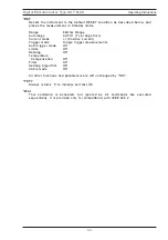
Page 54: ...rements Auto trigger mode Off Limits Off Datalog Off Temperature Compensation Off Filter Off Settling Algorithm Off Cable mode Off All other functions and parameters are left unchanged by RST TST Alwa...

Page 55: ...Gger DELay ABORt DataLog Commands MEMory DATA CLEAr DATA COUNt No of readings DATA COUNt DATA STATe ON OFF or 1 0 DATA STATe DATA first Datalog entry number last Datalog entry number ALL DATA POINts C...

Page 56: ...ENSe SETTling STATe ON OFF or 1 0 STATe COUNt No of readings COUNt LIMit No of digits LIMit System Related Commands SYSTem REMote LOCal BEEPer BEEPer STATe ON OFF or 1 0 BEEPer STATe VERSion TIME hh m...

Page 57: ...Transmitted Data output 4 not connected 5 GND Signal Ground 6 not connected 7 RTS Request To Send output 8 CTS Clear To Send input Operating Instructions Digital Microhmmeter Type DO7 PLUS 56 Test Eq...

Page 58: ...57 Operating Instructions...

Page 59: ...58...

Page 60: ...551A550 Rev 3...

Reviews: