

5s
10s
Step 2 - Adding Z
ū
m Mesh Devices to the Room
Adding Z
ū
m mesh devices to a room is quick and easy. Add devices to the room when
the room is in Joining mode. Joining mode is automatically enabled after a single-room
Z
ū
m system is started (see Step 1a). Joining mode can also be enabled manually (see
Step 1b).
The LEDs on all ac-powered devices in the system blink when the system is in Joining
mode.
NOTE
: A Z
ū
m mesh device can belong to only one room.
NOTE
: The Z
ū
m mesh device used to create the room is already part of the network. It
does not need to be added to the network.
To add a keypad to the room, press the top button 3 times, and then press and hold the
top button for 2 seconds. If the device is not factory fresh, hold the button for 10
seconds. Release the button when the LED lights. The LED blinks slowly to indicate that
it is part of the room and that the room is still in Joining Mode.
While the device searches for a network to join, the LED flashes fast. When the device
successfully joins a network, the LED lights for 3 seconds. After joining the room, the
LED turns off. Unlike the LED on ac-powered devices, the LED on battery-powered
devices does not slow blink to show that it has joined the network.
2s or 10s
Step 3 - Finishing the Single-Room Z
ū
m System
Press any button on a device that has already joined the network to end the setup
process (e.g., the top button of a keypad or the SETUP button of a J-box device that is
blinking its LED).
TEST
SETUP
Factory Reset
Press any button on a device that has already joined the network to end the setup
process (e.g., the top button of a keypad or the SETUP button of a J-box device that is
blinking its LED).
NOTE
: New-in-box devices do not need to be factory reset before joining a system.
To factory reset a keypad, press and hold the top and bottom buttons for 5 seconds until
the LED lights, and then release both buttons. Then, press and hold the bottom button
for 10 seconds until the LED lights.
Basic Room Setup
A basic single-room Z
ū
m system consists of Z
ū
m mesh devices, i.e., dimmers, switches,
keypads, and sensors. The Z
ū
m mesh devices in the room communicate directly with
each other without the need for a centralized gateway or processor.
To set up a new single-room Z
ū
m system, do the following:
Step 1a: Create a new single-room Z
ū
m system.
Step 2: Add Z
ū
m mesh devices to the room.
Step 3: Finish creating the single-room Z
ū
m system.
To modify an existing Z
ū
m system, do the following:
Step 1b: Place the system in Joining mode.
Step 2: Add Z
ū
m mesh devices to the room.
Step 3: Finish creating the single-room Z
ū
m system.
Step 1a – Creating a Single-Room Z
ū
m System
To create a new single-room Z
ū
m system, first form a new room.
NOTE
: This can be performed on only one device in the room.
NOTE
: The device that is used to create the room is automatically added to the room.
The device does not need to be added to the room.
NOTE
: A room can be created only from an ac-powered device.
Start a New Single-Room System with a Keypad, Dimmer, or Switch
Press the bottom button 5 times, and then press and hold the bottom button for
2 seconds. If the device is not factory fresh, hold the button for 10 seconds. Release the
button when the LED lights. The LED illuminates for 3 seconds and then slowly flashes to
indicate that the room is in Joining mode and that other devices can join the room.
Start a Single-Room System with a J-Box Device
Press the SETUP button 5 times, and then press and hold the SETUP button for
2 seconds. If the device is not factory fresh, hold the button for 10 seconds. Release the
button when the LED lights. The LED illuminates for 3 seconds and then slowly flashes to
indicate that the room is in Joining mode and that other devices can join the room.
2s or 10s
TEST
SETUP
2s or 10s
Step 1b – Expanding an Existing Single-Room Z
ū
m System
To allow other devices to join the room, place the single-room Z
ū
m system into Joining
mode. Joining mode can be enabled from any ac-powered device or battery keypad that
is already part of the room.
Expand a Single-Room Z
ū
m System Using a Keypad
To enter Joining mode, press and hold both the top and bottom buttons for 5 seconds,
wait for the LED to light, and then tap the top button once, and then the bottom button
once.
Pressing any button on a device that is part of the network takes the system out of
joining mode. Joining mode ends automatically after 4 minutes.
Expand a Single-Room Z
ū
m System Using a J-Box Device
To enter Joining mode, tap the SETUP button 2 times, and then tap the TEST button.
TEST
SETUP
TEST
SETUP
5s
5s
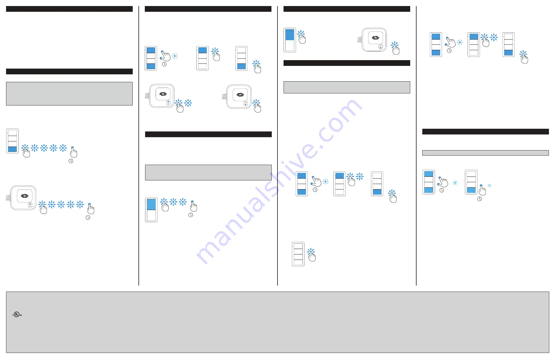
Creating Scenes
Setting the scenes alters the default presets to allow customization of the brightness
levels when a button is pressed. Set scenes using the End-User Method, Manual
Method, or the Remote Method.
NOTE
: Only load controllers bound to this keypad can be in the keypad’s scenes.
NOTE
: All load controllers bound to this keypad must be in this keypad’s scenes.
End-User Method
The end-user method allows fast and efficient setting of the presets. The end-user
method is only applicable to SCENE 2 and SCENE 3. It cannot be used on 2-button
keypads, and cannot be used to save the ON (scene 1 preset) scene.
To customize presets, do the following:
1. Go to each load controller that is bound to the keypad and set the loads to the
desired brightness level for the scene.
2. Hold the SCENE 2 or SCENE 3 button for 5 seconds to save the current light levels
to the pressed button.
Manual Method
Use the Manual Method when each load controller is physically accessible.
To customize presets, do the following:
1. Using the keypad in the room, hold the top and bottom buttons simultaneously for
5 seconds until the LED flashes. Then press the top button 2 times, and then the
bottom button once.
• The keypad blinks its LED 2 times every 2 seconds.
• Load controllers that are linked with the keypad fast blink their LED.
2. Adjust the load levels.
• Using the dimmers, adjust all load levels in the room by pressing and holding the
top button to raise the light level or the bottom button to lower the light level.
• Using the switches, turn the loads on or off by pressing the top button to turn
the load on or the bottom button to turn the load off.
• Using the load controllers, press and hold the TEST button on the J-box device
to cycle-dim the load.
3. Using the keypad in the room, press the ON, SCENE 2, or SCENE 3 button that
should recall the current levels. This saves the levels to the scene.
4. Repeat steps 2 and 3 for all scenes.
5. Tap the bottom button on the keypad 3 times to exit scene setting.
ON
SCENE 2
SCENE 3
OFF
5s
Remote Method
Use the Remote Method when load controllers are not physically accessible.
To customize presets, do the following:
1. Using the keypad in the room, hold the top and bottom buttons simultaneously for
5 seconds until the LED flashes. Then press the top button 2 times, and then the
bottom button once.
3. Hold the bottom button for 3 seconds until one of the loads in the room begins to
flash. The load that is flashing is the "Selected" load.
4. Tap the bottom button to cycle through the loads until the desired load flashes. The
load flashes twice and then returns to its previous light level to indicate that it is
selected.
5. Adjust the brightness by holding the top button on the keypad to raise the light
level or holding the bottom button to lower the light level.
6. To save the light level to a scene, press the ON, SCENE 2, or SCENE 3 button.
7. Press the bottom button to select the next load controller that is bound to this
keypad. The load flashes twice and then returns to its previous light level to
indicate that it is selected.
8. Repeat steps 4 through 6 for additional load controllers until all load controllers and
all scenes are defined.
9. Tap the bottom button 3 times to exit.
This product is Listed to applicable UL
®
Standards and requirements tested by Underwriters
Laboratories Inc.
Ce produit est homologué selon les normes et les exigences UL applicables par Underwriters
Laboratories Inc.
Federal Communications Commission (FCC) Compliance Statement
This device complies with part 15 of the FCC Rules. Operation is subject to the following two
conditions: (1) This device may not cause harmful interference, and (2) this device must accept any
interference received, including interference that may cause undesired operation.
CAUTION
: Changes or modifications not expressly approved by the manufacturer responsible for
compliance could void the user’s authority to operate the equipment.
NOTE
: This equipment has been tested and found to comply with the limits for a Class A digital
device, pursuant to part 15 of the FCC Rules. These limits are designed to provide reasonable
Crestron Electronics, Inc.
Installation Guide - DOC. 7865A
15 Volvo Drive Rockleigh, NJ 07647
(2047761)
Tel: 888.CRESTRON
02.17
Fax: 201.767.7576
Specifications subject to
www.crestron.com
change without notice.
protection against harmful interference when the equipment is operated in a commercial environment.
This equipment generates, uses, and can radiate radio frequency energy and, if not installed and used
in accordance with the instruction manual, may cause harmful interference to radio communications.
Operation of this equipment in a residential area is likely to cause harmful
interference in which case the
user will be required to correct the interference at his own expense.
Industry Canada (IC) Compliance Statement
CAN ICES-3(A)/NMB-3(A)
The product warranty can be found at www.crestron.com/warranty.
The specific patents that cover Crestron products are listed at patents.crestron.com.
Certain Crestron products contain open source software. For specific information, please visit
www.crestron.com/opensource.
Crestron, the Crestron logo, and Z
ū
m are either trademarks or registered trademarks of Crestron
Electronics, Inc. in the United States and/or other countries. UL and the UL logo are either trademarks
or registered trademarks of Underwriters Laboratories, Inc. in the United States and/or other countries.
Other trademarks, registered trademarks, and trade names may be used in this document to refer to
either the entities claiming the marks and names or their products. Crestron disclaims any proprietary
interest in the marks and names of others. Crestron is not responsible for errors in typography or
photography.
This document was written by the Technical Publications department at Crestron.
©2017 Crestron Electronics, Inc.


