background image

Connect

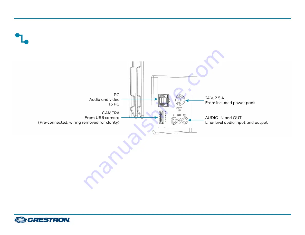
Make the necessary connections as called out in the following diagram. Connect power last. Once all connections are made, pivot the soundbar up to the

wall bracket until the soundbar locks into place.

l

PC: Connect the included USB cable to the PC port and to a USB port on the computer. For optimal results, use a USB 3.0 connection.

l

CAMERA: The integrated camera is already connected from the factory.

l

24 V, 2.5 A: Connect the power pack to the 24 V, 2.5 A power input and to an AC power outlet.

l

AUDIO IN and AUDIO OUT: The soundbar provides unbalanced, stereo, analog input and output jacks (3.5 mm TRS mini-phone). The AUDIO IN port

accommodates an optional line-level audio source which feeds to the internal amplifier and speakers without a volume control or other signal

processing. The AUDIO OUT port provides a line-level signal for an optional assistive listening system and carries the same audio signal as the

soundbar speakers.

6

UC-SB1-CAM

Quick Start

UC Video Conference Smart Soundbar & Camera

Summary of Contents for UC-SB1-CAM

Page 1: ...thority to operate the equipment NOTE This equipment has been tested and found to comply with the limits for a Class B digital device pursuant to part 15 of the FCC Rules These limits are designed to provide reasonable protection against harmful interference in a residential installation This equipment generates uses and can radiate radio frequency energy and if not installed and used in accordanc...

Page 2: ...nited States and or other countries Intertek is either a trademark or registered trademark of Intertek Group in the United States and or other countries The ETL logo is either a trademark or registered trademark of Intertek Testing Services NA in the United States and or other countries UL is either a trademark or registered trademark of Underwriters Laboratories Inc in the United States and or ot...

Page 3: ...ll In the Box 1 UC SB1 CAM UC Video Conference Smart Soundbar Camera Additional Items 4 Anchor Drywall Plastic 3 8 in x 1 2 in 2052565 1 Cable USB 3 0 A B 6 ft 1 83 m 2053077 2 Foot 2 3 in x 0 96 in x 0 15 in Rubber 2052169 1 Key Anchor 4529654 1 Power Cord 5 ft 10 in 1 78 m 2042043 1 Power Pack 24 VDC 2 5 A 100 240 VAC 2045873 4 Screw 8 AB x 1 1 2 in Pan Head Combo 2052567 1 Template Overlay 4529...

Page 4: ... on a wall The soundbar has the following dimensions Place on a Flat Surface If the soundbar is to be placed on a flat surface attach the included rubber feet to the bottom of the soundbar as shown 2 UC SB1 CAM Quick Start UC Video Conference Smart Soundbar Camera ...

Page 5: ...4 in 19 mm minimum clearance above the top of the soundbar Use the included template to allow for sufficient clearance between the soundbar and display device The following tools are required to mount the soundbar l Drywall saw not included l Drill with 5 16 in bit not included A template is included to provide drill hole locations for the included mounting hardware 1 Attach the template to the de...

Page 6: ...ywall saw to make a cutout in the wall for the soundbar cables The cutout in the center of the template provides adequate access for all of the required cabling 4 Install the four included anchors and screws into the drilled pilot holes 5 Place the soundbar face down and pivot the wall bracket away from the soundbar 4 UC SB1 CAM Quick Start UC Video Conference Smart Soundbar Camera ...

Page 7: ...secured to the wall 7 Route the cables through the cable cutout and connect the cables as described in Connect NOTE The included power pack s cord is typically routed from the wall opening through the cable cutout to the soundbar 5 UC SB1 CAM Quick Start UC Video Conference Smart Soundbar Camera ...

Page 8: ...tory l 24 V 2 5 A Connect the power pack to the 24 V 2 5 A power input and to an AC power outlet l AUDIO IN and AUDIO OUT The soundbar provides unbalanced stereo analog input and output jacks 3 5 mm TRS mini phone The AUDIO IN port accommodates an optional line level audio source which feeds to the internal amplifier and speakers without a volume control or other signal processing The AUDIO OUT po...

Page 9: ...and speaker turns the two outer segments of the status bar red l Muting the microphone turns the center of the status bar red System Control The soundbar can be used in a BYOD scenario where the soundbar is connected to an end user s PC over USB The soundbar will pass both camera and bidirectional mic and speaker audio across a single USB connection Visit the Product Page Scan the QR code to visit...

Page 10: ...ment The product warranty can be found at www crestron com warranty The specific patents that cover Crestron products are listed at www crestron com legal patents Certain Crestron products contain open source software For specific information visit www crestron com opensource Crestron and the Crestron logo are either trademarks or registered trademarks of Crestron Electronics Inc in the United Sta...

Reviews: