background image


This document was prepared and written by the Technical Documentation department at: 


Crestron Electronics, Inc. 

15 Volvo Drive 

Rockleigh, NJ 07647 

1-888-CRESTRON 


Regulatory Compliance

Federal Communications Commission (FCC) Compliance Statement

This Class B digital apparatus complies with Canadian ICES-003.

Cet appareil numérique de la classe B est conforme à la norme NMB-003 du Canada.

Industry Canada (IC) Compliance Statement

This device complies with part 15 of the FCC rules. Operation is subject to the following conditions:

(1) this device may not cause harmful interference and (2) this device must accept any interference received, 

including interference that may cause undesired operation.

CAUTION:

  Changes or modifications not expressly approved by the manufacturer responsible for compliance 

could void the user’s authority to operate the equipment. 

NOTE:

  This equipment has been tested and found to comply with the limits for a Class B digital device, 

pursuant to part 15 of the FCC rules. These limits are designed to provide reasonable protection against harmful 

interference in a residential installation. This equipment generates, uses and can radiate radio frequency energy 

and if not installed and used in accordance with the instructions, may cause harmful interference to radio 

communications. However, there is no guarantee that interference will not occur in a particular installation. If 

this equipment does cause harmful interference to radio or television reception, which can be determined by 

turning the equipment off and on, the user is encouraged to try to correct the interference by one or more of the 

following measures:

Reorient or relocate the receiving antenna
Increase separation between the equipment and the receiver
Connect the equipment into an outlet on a circuit different from that to which the receiver is connected
Consult the dealer or an experienced radio/TV technician for help

As of the date of manufacture, the TPMC-V12 and TPMC-V15 have been tested and found to comply with 

specifications for CE marking and standards per EMC and Radiocommunications Compliance Labelling.


Crestron, the Crestron logo, CresCAT, Cresnet, Crestron Home, Crestron Toolbox, DigitalMedia, Intermedia Delivery System, 

QuickMedia, SIMPL Windows, SystemBuilder, TouchPoint, V-Panel, VisionTools and VT Pro-e are trademarks or registered 

trademarks of Crestron Electronics, Inc. in the United States and other countries. Adobe, Acrobat and Flash are either trademarks or 

registered trademarks of Adobe Systems Inc. in the United States and/or other countries. Microsoft, Excel, Internet Explorer, 

PowerPoint, XP, Windows and Windows Media are either trademarks or registered trademarks of Microsoft Corporation in the United 

States and/or other countries. Java is either a trademark or a registered trademark of Oracle and/or its affiliates in the United States 

and/or other countries. Other trademarks, registered trademarks and trade names may be used in this document to refer to either the 

entities claiming the marks and names or their products. Crestron disclaims any proprietary interest in the marks and names of others.


©2011 Crestron Electronics, Inc. 


Summary of Contents for TPMC-V12 & TPMC-V15

Page 1: ...Crestron TPMC V12 TPMC V15 V Panel Integrated12 15 TouchScreens Operations Guide...

Page 2: ...on which can be determined by turning the equipment off and on the user is encouraged to try to correct the interference by one or more of the following measures Reorient or relocate the receiving ant...

Page 3: ...gramming with SIMPL Windows 50 Programming with VisionTools 53 Embedded Applications 57 Defaults for Embedded Windows Applications 59 Programming Embedded Windows Applications 59 Uploading and Upgradi...

Page 4: ......

Page 5: ...2 SVGA TPMC V12 and 15 widescreen WXGA TPMC V15 displays with astounding 24 bit color graphics and video advanced device control apps and objects streaming multimedia Web browsing and IP intercom cohe...

Page 6: ...centers and much more providing a wide open canvas for the creation of custom control screens tailored to the needs of the end user Touch screens do away with piles of remote controls cryptic control...

Page 7: ...n and system integration possibilities Integrated Video For monitoring security cameras or watching a DVD or television the TPMC V12 15 provides multiple ways to view video signals right on the touch...

Page 8: ...ideo connectivity is only available through the TPMC V IMCW interface module 1 Item included refer to individual product specifications for additional information 2 The TPMC V12 15 models include 1 TP...

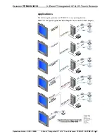
Page 9: ...ch Screens Applications The following diagrams show a TPMC V12 in a typical application TPMC V12 in a Typical Application Each Diagram Varies with LAN Cable Length Operations Guide DOC 6940B V Panel I...

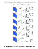
Page 10: ...tron TPMC V12 V15 The following diagrams show a TPMC V15 in a typical application TPMC V15 in a Typical Application Each Diagram Varies with LAN Cable Length 6 V Panel Integrated 12 15 Touch Screens T...

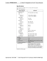
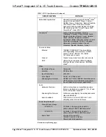
Page 11: ...TPMC V15 700 1 Color Depth 24 bit 16 7 million colors Illumination Backlit fluorescent Viewing Angle TPMC V12 89 horizontal 89 vertical TPMC V15 85 horizontal 85 vertical Touch Screen Resistive membra...

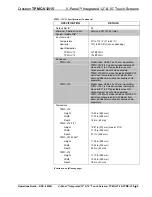
Page 12: ...de for control and console USB USB 2 0 host supports USB HID Human Interface Device class devices USB flash drives3 Video Input Signal Types Composite Formats NTSC or PAL Input Resolutions 480i 576i C...

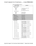
Page 13: ...ont bezel additional mounting accessories sold separately TPMC V15 Plastic case VESA 75 x 75 mm mountable TPMC V15 TILT model includes tabletop tilt stand with 0 to 35 adjustable screen tilt optional...

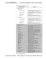
Page 14: ...Panel Integrated 12 VESA Mount Touch Screen White TPMC V12 TILT B V Panel Integrated 12 Tilt Touch Screen Black TPMC V12 TILT W V Panel Integrated 12 Tilt Touch Screen White TPMC V12 WALL B V Panel I...

Page 15: ...ALL BB V15 Pre Construction Wall Mount Back Box for TPMC V15 WALL BBI V12 Pre Construction Wall Mount Back Box for TPMC V12 WALL International Version BBI V15 Pre Construction Wall Mount Back Box for...

Page 16: ...h drive 4 May be powered by power pack or Cresnet network power not both 5 Item included refer to individual product specifications for additional information 6 The latest software versions can be obt...

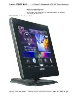
Page 17: ...Physical Description This section provides information on the connections controls and indicators available on your TPMC V12 15 TPMC V12 TILT Physical View Shown in Black Operations Guide DOC 6940B V...

Page 18: ...V Panel Integrated 12 15 Touch Screens Crestron TPMC V12 V15 TPMC V12 WALL Physical View Shown in White 14 V Panel Integrated 12 15 Touch Screens TPMC V12 TPMC V15 Operations Guide DOC 6940B...

Page 19: ...Crestron TPMC V12 15 V Panel Integrated 12 15 Touch Screens TPMC V15 TILT Physical View Shown in Black Operations Guide DOC 6940B V Panel Integrated 12 15 Touch Screens TPMC V12 TPMC V15 15...

Page 20: ...15 Touch Screens Crestron TPMC V12 V15 TPMC V15 WALL Physical View Shown in White TPMC V15 Physical View Rear Showing Connector Ports 16 V Panel Integrated 12 15 Touch Screens TPMC V12 TPMC V15 Opera...

Page 21: ...Integrated 12 15 Touch Screens TPMC V12 Overall Dimensions Front and Side Views 11 72 in 298 mm 10 22 in 260 mm Microphone 1 2 1 66 in 42 mm Operations Guide DOC 6940B V Panel Integrated 12 15 Touch...

Page 22: ...OTE In the illustration above the TPMC V12 is shown with the rear cover removed When making cable connections to the TPMC V12 it will be necessary to remove the cover by first removing the four screws...

Page 23: ...l Integrated 12 15 Touch Screens TPMC V12 TILT Overall Dimensions Front View 11 72 in 298 mm 10 22 in 260 mm 10 81 in 275 mm Microphone 1 2 Operations Guide DOC 6940B V Panel Integrated 12 15 Touch Sc...

Page 24: ...h Screens Crestron TPMC V12 V15 TPMC V12 TILT Overall Dimensions Side View 64 00 in 1 00 1 63 m 35 Max Tilt Angle 1 66 in 42 mm 8 11 in 206 mm 20 V Panel Integrated 12 15 Touch Screens TPMC V12 TPMC V...

Page 25: ...Integrated 12 15 Touch Screens TPMC V15 Overall Dimensions Front and Side Views 1 85 in 47 mm 11 10 in 282 mm 15 33 in 390 mm Microphone 1 2 Operations Guide DOC 6940B V Panel Integrated 12 15 Touch...

Page 26: ...OTE In the illustration above the TPMC V15 is shown with the rear cover removed When making cable connections to the TPMC V15 it will be necessary to remove the cover by first removing the four screws...

Page 27: ...l Integrated 12 15 Touch Screens TPMC V15 TILT Overall Dimensions Front View 11 10 in 282 mm 15 33 in 390 mm 11 69 in 297 mm Microphone 1 2 Operations Guide DOC 6940B V Panel Integrated 12 15 Touch Sc...

Page 28: ...5 TPMC V15 TILT Overall Dimensions Side View 35 Max Tilt Angle 64 00 in 1 00 1 63 m 1 85 in 47 mm 8 11 in 206 mm TPMC V12 15 Overall Dimensions Rear View V15 Shown 3 5 6 4 24 V Panel Integrated 12 15...

Page 29: ...9 meter Siamese Cable The TPMC V12 15 TILT models include 1 TPMC V CBL S6 6 foot 1 8 meter Siamese Cable The TPMC V12 15 WALL models do not include any cable 4 For wiring between the TPMC V12 and int...

Page 30: ...D of the TPMC V12 15 has been factory set to 03 The Net IDs of multiple TPMC V12 15 devices in the same system must be unique The Net ID is set using the internal setup menu refer to Cresnet on page 3...

Page 31: ...when you see the Preparing to Load Project message Maintain touch until after the countdown when the message will change to Loading Setup Screen 2 If the project has a button defined for this purpose...

Page 32: ...ct load process has completed Standby will then be enabled again To exit the setup menu and return to the program touch Exit located at the bottom of the setup menu To save any changes and reboot the...

Page 33: ...NOTE To use the on screen keyboard for security settings touch Keyboard on the startup menu before touching Security Security Setup Window Touch Setup Connections to open the Network Connections wind...

Page 34: ...ap Drive Letter drop box 3 Enter a user name and password 4 Touch the Remember and reconnect on startup checkbox if so desired 5 Touch OK to enable the new network connection and return to the Network...

Page 35: ...ected to a control system via Ethernet Communication mode is factory set to Disable The Cresnet network identity number Cresnet ID is displayed in the Cresnet Setup window Cresnet ID is a two digit he...

Page 36: ...te calibration As each new crosshair is touched the next will appear After the upper left crosshairs will appear in the upper center upper right middle left screen center middle right lower left lower...

Page 37: ...ch screen response at 17 points on the screen Each button on the screen will light when touched Touch Return to exit the test screen Touch Screen Test Window Display Output Touching Display Output sho...

Page 38: ...the Project to area of the Load New Project section you can choose the location where your uncompressed project files will be stored The default file location is the internal flash NOTE If there is a...

Page 39: ...ded from a network drive USB device or flash drive Touch Load to load the new firmware Video Video input is selected and adjusted from this window If it is not already selected touch the Video tab to...

Page 40: ...utside edge of the active picture area was pushed out past the edge of the display area The average or targeted overscan loss is about 5 to 10 of the image on each edge Digital images have nearly elim...

Page 41: ...Clicks as well as a Mute button for the Microphone input For Local Audio Microphone Control check boxes are provided to Enable digital microphone noise suppression and Enable microphone acoustic echo...

Page 42: ...riate for most Internet sites Low Minimal safeguards and warning prompts are provided Most content is downloaded and run without prompts All active content can run Appropriate for sites you absolutely...

Page 43: ...y correct this error Other restrictions may also cause this error so this may not prevent all occurrences NOTE The TPMC V12 15 supports automatic connection to the VNC server when the VNC View applica...

Page 44: ...ow Changes are made in real time and there is typically no need to reboot The Ethernet address and mask are displayed on this screen Ethernet Setup Window To configure the Ethernet adapter touch its n...

Page 45: ...TCP monitors and ensures correct transfer of data IP receives the data from TCP breaks it up into packets and ships it off to a network The IP address is a unique number consisting of four parts calle...

Page 46: ...xed controllable network This helps maintain communication stability between Ethernet devices IP Table Touch IP Table on the setup menu to open the IP Table Setup window Edit remove or enter a control...

Page 47: ...required for Ethernet communication Sharing Touch Sharing to open the Configure Shared Folders window This window is used to set up shared folders Sharing enables remote computers to view and or modi...

Page 48: ...o reactivate the touch screen Screen Brightness Details The Screen Brightness can be varied from 0 to 100 To increase the brightness touch Up To decrease the brightness touch Down Misc Controls Detail...

Page 49: ...5 to 100 with a default value of 90 The Default button restores the original Screen Position and Translucence settings as well as enabling display of Network messages A Test Message button lets you se...

Page 50: ...program After reboot the position of the on screen keyboard will revert to the defaults set in the VT Pro e or SIMPL Windows program The size will revert to the largest as determined by the firmware...

Page 51: ...sted in the table of specifications Connect the Device The TPMC V12 15 can be connected using the included TPMC V IMCW interface module or if the video inputs provided by the TPMC V IMCW are not neede...

Page 52: ...ond 175 feet 53 meters NOTE For wiring between the TPMC V15 and interface module use a TPMC V CBL S Siamese Cable CresCAT CresCAT D HP CresCAT QM DM CBL or quality CAT5e CAT6 CAT5e 6 requires an addit...

Page 53: ...Allen Screws for Tilt Tension Adjustment Recommended Cleaning Keep the surface of the touch screen free of dirt dust or other materials that could degrade optical properties Long term contact with abr...

Page 54: ...g with Crestron SystemBuilder SystemBuilder is a comprehensive programming environment Appropriate for most systems it can quickly and easily generate a complete working program including both control...

Page 55: ...of the control system displays the device in the appropriate slot s with a default Net ID or IP ID as shown in the following illustration NOTE In the following illustration there is both an Ethernet d...

Page 56: ...evice Each TPMC V12 15 is assigned a different Net ID or IP ID number as it is added 3 If necessary double click a device to open the Device Settings window and change the Net ID or IP ID as shown in...

Page 57: ...ost advanced VT Pro e high performance programming technique involving the TPMC V12 15 is the concept of multi mode objects A multi mode object i e button legend etc is an object drawn on a VT Pro e p...

Page 58: ...color table In this way any one of the specific 256 color table locations is assigned to a pixel A 16 bit highcolor system is considered sufficient to provide life like colors It is encoded using 5 b...

Page 59: ...ion in image size will save a considerable amount of memory space for your project In VT Pro e the Compress checkbox permits the image to be compressed when compiling The 16 Bits checkbox converts a 2...

Page 60: ...u cannot enter Chinese characters interspersed with numbers You can enter Chinese characters or numbers in separate strings or you can pad each number with x00 to make it multibyte and then combine it...

Page 61: ...hin embedded applications are not supported by the TPMC V12 15 A number of third party or in house applications are embedded in a VT Pro e TPMC V12 15 project Refer to illustration on the following pa...

Page 62: ...be assigned to each application to dynamically change position and size One digital feedback join or one analog join can be assigned to dynamically show hide an application Embedded Applications in Pr...

Page 63: ...nd Size in the Embedded Application Properties window to point to your new location Sample of an Embedded Application Properties Window Programming Embedded Windows Applications The following diagram...

Page 64: ...ion being open but the state of the toggle remaining low so a one shot is used to set the state of the toggle if the embedded application is opened in this way For example the user presses button 10 a...

Page 65: ...thernet Communication PC Running Crestron Toolbox LAN TPMC V12 15 The TPMC V12 15 connects to PC via Ethernet 1 Enter the IP address IP mask and default router of the TPMC V12 15 via Crestron Toolbox...

Page 66: ...drive Program Checks Actions that can be performed on the TPMC V12 15 vary depending on whether it is connected via Cresnet or Ethernet Cresnet Connections For Cresnet connections using Crestron Toolb...

Page 67: ...ere is no e mail client installed on the TPMC V12 15 so email based viruses cannot be executed 5 Viruses that attack web FTP servers The TPMC V12 15 does not run a web or FTP server and is therefore n...

Page 68: ...rogram Use Crestron Toolbox to poll the network Verify that the Cresnet ID for the touch screen is properly set to match the Net ID in the SIMPL program Touch screen is not responding Touch screen Cre...

Page 69: ...only Crestron power supplies for Crestron equipment Failure to do so could cause equipment damage or void the Crestron warranty CAUTION Provide sufficient power to the system Insufficient power can l...

Page 70: ...e latest version of all documents mentioned within the guide can be obtained from the Crestron Web site www crestron com manuals List of Related Reference Documents DOCUMENT TITLE 2 Series Control Sys...

Page 71: ...ds data or instructions from or to another computer b for local campus or wide area network Internet or Web hosting services or c pursuant to any rental sharing or service bureau arrangement The Softw...

Page 72: ...ty 90 days from the date of receipt and b that any hardware accompanying the Software will be subject to its own limited warranty as stated in its accompanying written material Crestron shall at its o...

Page 73: ...tilt heads and power supplies are covered for a period of one 1 year touch screen display and overlay components are covered for 90 days batteries and incandescent lamps are not covered This warranty...

Page 74: ...upgrade any transfer must also include all prior versions of the SOFTWARE o EXPORT RESTRICTIONS You acknowledge that SOFTWARE is subject to U S export jurisdiction You agree to comply with all applic...

Page 75: ...personally identifies you Internet Gaming Update Features If the SOFTWARE provides and you choose to utilize the Internet gaming or update features within the SOFTWARE it is necessary to use certain...

Page 76: ...Crestron Electronics Inc Operations Guide DOC 6940B 15 Volvo Drive Rockleigh NJ 07647 2027403 Tel 888 CRESTRON 06 11 Fax 201 767 7576 Specifications subject to www crestron com change without notice...

Reviews: