background image

Crestron 

IM-RXV1-M & IM-RXV3-M


iMedia Receiver with Video & Mic Input


Uploading and Upgrading 

Crestron recommends using the latest programming software and that each device 
contains the latest firmware to take advantage of the most recently released features. 
However, before attempting to upload or upgrade it is necessary to establish 
communication. Once communication has been established, files (for example, 
programs or firmware) can be transferred to the device). Finally, program checks can 
be performed (such as creating an IP table) to ensure proper functioning. 

Establishing Communication 

Use Crestron Toolbox for communicating with the IM-RXV1-M and IM-RXV3-M; 
refer to the Crestron Toolbox help file for details. There are two methods of 
communication. 

Direct Serial Communication   

NOTE:

  Required for initial setup of Ethernet parameters. 

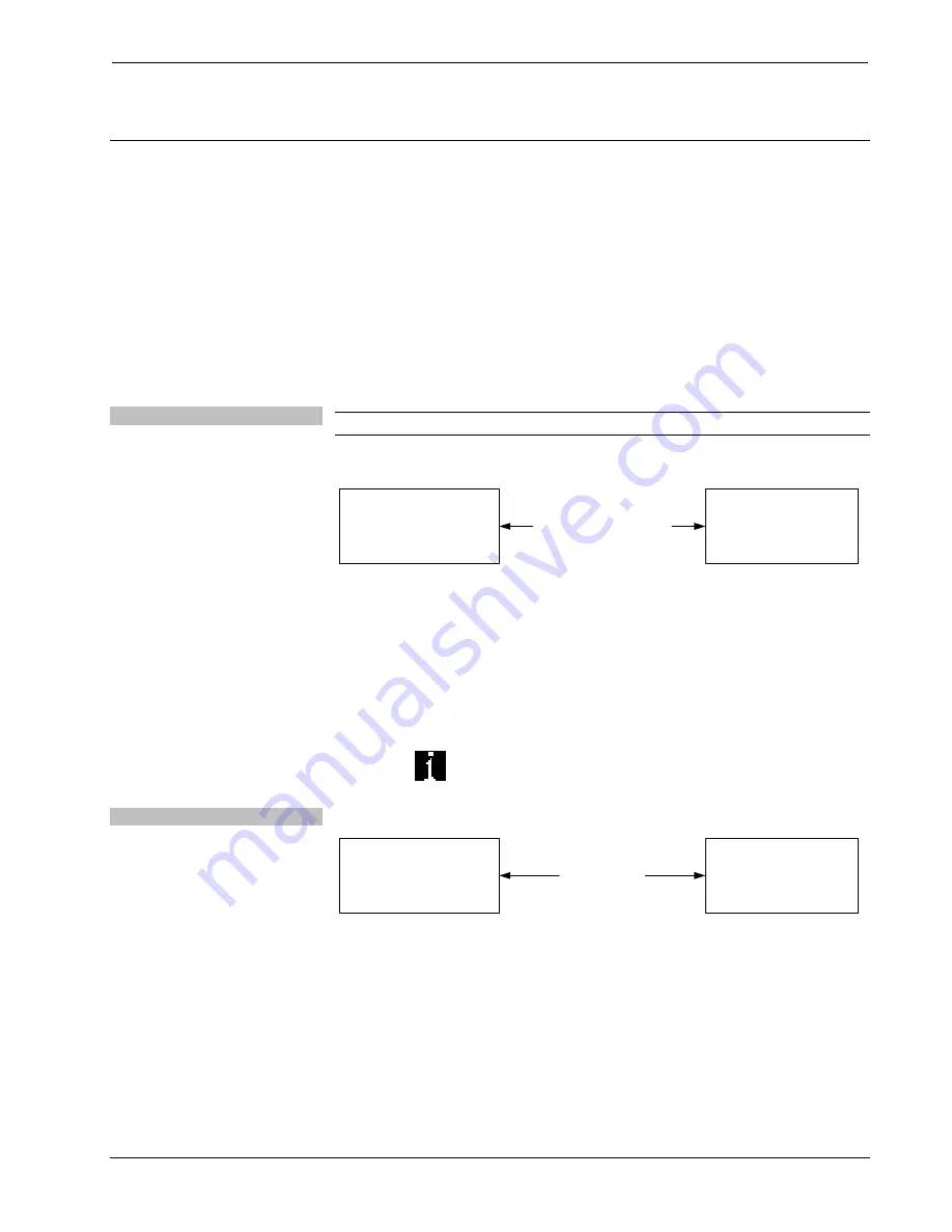
Direct Serial Communication 

IM-RXV1-M

OR

IM-RXV3-M

PC RUNNING

CRESTRON TOOLBOX

SERIAL VIA CRESTRON

CABLE STCP-502PC

OR EQUIVALENT


• 

The 

COMPUTER

 port on the IM-RXV1-M and IM-RXV3-M connects to 

the serial port on the PC via a serial cable (Crestron STCP-502PC or 
equivalent). 

• 

Use the Address Book in Crestron Toolbox to create an entry using the 
expected serial communication protocol (RS-232, auto-detect baud rate, no 
parity, 8 data bits, 1 stop bit, XON/XOFF disabled, RTS/CTS enabled). 

• 

Display the IM-RXV1-M or IM-RXV3-M’s “System Info” window (click 

the 

 icon); communications are confirmed when the device information 

is displayed. 

TCP/IP Communication 


Ethernet Communication 

IM-RXV1-M

OR

IM-RXV3-M

PC RUNNING

CRESTRON TOOLBOX

ETHERNET


• 

Establish serial communication between IM-RXV1-M or IM-RXV3-M and 
PC. 

• 

Enter the IP address, IP mask and default router of the IM-RXV1-M or 
IM-RXV3-M via the Crestron Toolbox (

Functions | Ethernet 

Addressing

); otherwise enable DHCP. 

• 

Confirm Ethernet connections between IM-RXV1-M or IM-RXV3-M and 
PC. If connecting through a hub or router, use CAT5 straight through cables 
with 8-pin RJ-45 connectors. Alternatively, use a CAT5 crossover cable to 
connect the two 

LAN 

ports directly without using a hub or router. 

Operations & Installation Guide – DOC. 6593A 

iMedia Receiver: IM-RXV1-M & IM-RXV3-M  

  17 

Summary of Contents for IM-RXV1-M

Page 1: ...Crestron IM RXV1 M IM RXV3 M iMediaReceiverwithVideoandMicInput Operations Installation Guide...

Page 2: ...by the Technical Documentation department at Crestron Electronics Inc 15 Volvo Drive Rockleigh NJ 07647 1 888 CRESTRON All brand names product names and trademarks are the property of their respectiv...

Page 3: ...3 Installation 14 Hardware Hookup 15 System Configuration 16 Earliest Version Software Requirements for the PC 16 iMedia Wizard Configuration 16 Uploading and Upgrading 17 Establishing Communication 1...

Page 4: ......

Page 5: ...low cost Models with one IM RXV1 M or three IM RXV3 M IM transmitter inputs are available Features and Functions A simple affordable solution for single display multimedia presentation iMedia Transpo...

Page 6: ...low the audio signal to be connected directly to inputs on the display device or fed to a pair of powered speakers Onboard digital signal processing affords adjustment of audio levels plus bass treble...

Page 7: ...edia transmitters without composite video inputs The IM RXV1 M and IM RXV3 M can be placed on a table or mounted to a surface using the included brackets These receivers can also be mounted to a pipe...

Page 8: ...ations SPECIFICATION DETAILS RGB Gain 0 dB 75 ohm termination Formats RGBHV RGBS or RGsB Resolution 1024 x 768 60 Hz with maximum cable length of 84 feet 1600 x 1200 60 Hz with maximum cable length of...

Page 9: ...trol 2 XPanel and RoomView applications Power Requirements 3 Amps 18 Volts DC Environmental Temperature 41 to 104 F 5 to 40 C Humidity Thermal Dissipation 10 to 90 RH non condensing 100 BTU Hr Enclosu...

Page 10: ...tion This section provides information on the connections controls and indicators available on your IM RXV1 M and IM RXV3 M IM RXV1 M Physical Views Front and Rear IM RXV3 M Physical Views Front and R...

Page 11: ...Media Receiver with Video Mic Input IM RXV1 M IM RXV3 M Overall Dimensions 7 69 in 19 53 cm 8 75 in 22 23 cm 1 62 in 4 10 cm Continued on following page Operations Installation Guide DOC 6593A iMedia...

Page 12: ...on IM RXV3 M The peaking control is used during setup for video cable length compensation Refer to iMedia Wizard Configuration on page 16 for additional details 2 AUDIO G L R 1 5 pin 3 5mm detachable...

Page 13: ...ed indicates activity on any input port 9 IR LED Red indicates activity on IR port 10 MIC 1 3 5mm TRS mini phone jack Balanced mono line level audio input Maximum input level 2 Vrms balanced 1 Vrms un...

Page 14: ...DTR Data Terminal Ready 5 Common GND Ground 6 From IM RXV1 3 M DSR Data Set Ready 7 From IM RXV1 3 M RTS Request To Send 8 To IM RXV1 3 M CTS Clear To Send 9 To IM RXV1 3 M RI Ring Indicator 14 VIDEO...

Page 15: ...devices must accept any interference received including interference that may cause undesired operation This equipment has been tested and found to comply with the limits for a Class B digital device...

Page 16: ...restron products using the iMedia transport system are capable of sending and receiving iMedia signals via CresCAT IM cable Installation of any iMedia device is as simple as installing one iMedia cabl...

Page 17: ...w of 15 ns per 100 meters is not exceeded NOTE For proper operation and performance of every iMedia system always use CresCAT IM cable Maximum Resolution and Cable Length RESOLUTION REFRESH RATE HZ PI...

Page 18: ...st be installed prior to mounting Complete the following procedure to attach the brackets to the unit The only tool required is a 1 Phillips screwdriver To install the ears 1 There are screws that sec...

Page 19: ...ther high quality low skew CAT5e CAT6 wiring may also be used with varying performance Hardware Connections Rear 1 2 3 G POWER FROM POWER SUPPLY 18 VDC 3 0 A RELAY OUTPUT TWO LOW VOLTAGE CONTACT CLOSU...

Page 20: ...ptional but recommended iMedia Wizard part of Crestron SystemBuilder version 3 0 or later requires SIMPL Windows VisionTools Pro e Crestron Database and Crestron Engraver with Systembuilder Templates...

Page 21: ...OMPUTER port on the IM RXV1 M and IM RXV3 M connects to the serial port on the PC via a serial cable Crestron STCP 502PC or equivalent Use the Address Book in Crestron Toolbox to create an entry using...

Page 22: ...s For details on upgrading firmware refer to the Crestron Toolbox help file Check the Crestron website to find the latest firmware New users may be required to register to obtain access to certain are...

Page 23: ...ter Select correct input on transmitter Incorrect cable connection Verify display device connection Video from source is garbled or no output Verify maximum iMedia cable length Peak adjustment incorre...

Page 24: ...e http www crestron com onlinehelp to ask questions about Crestron products First time users will need to establish a user account to fully benefit from all available features Future Updates As Crestr...

Page 25: ...commands data or instructions from or to another computer b for local campus or wide area network internet or web hosting services or c pursuant to any rental sharing or service bureau arrangement Th...

Page 26: ...f ninety 90 days from the date of receipt and b that any hardware accompanying the Software will be subject to its own limited warranty as stated in its accompanying written material Crestron shall at...

Page 27: ...d for 90 days batteries and incandescent lamps are not covered This warranty extends to products purchased directly from CRESTRON or an authorized CRESTRON dealer Purchasers should inquire of the deal...

Page 28: ...on Electronics Inc Operations Installation Guide DOC 6593A 15 Volvo Drive Rockleigh NJ 07647 2018247 Tel 888 CRESTRON 07 07 Fax 201 767 7576 Specifications subject to www crestron com change without n...

Reviews: