7-13
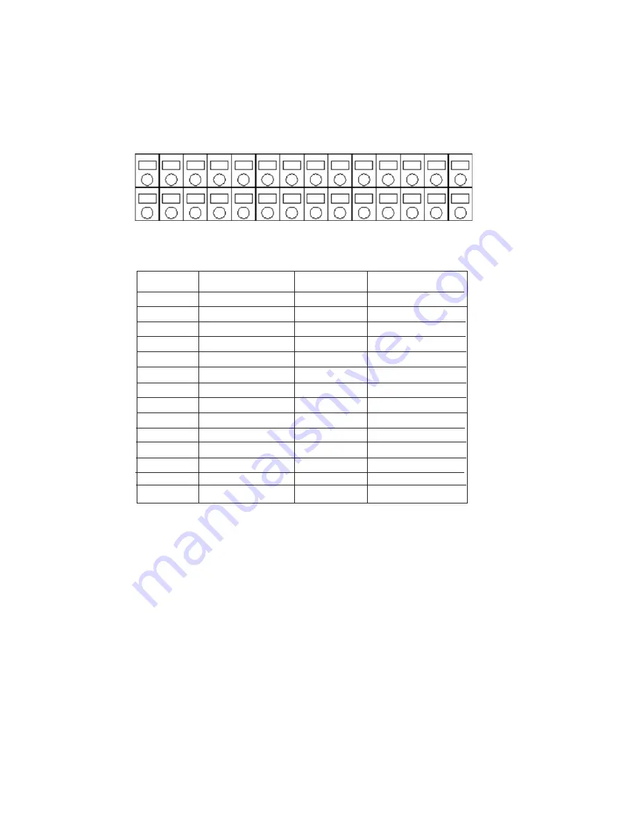
28 27 26 25 24 23 22 21 20 19 18 17 16 15
1 2 3
4 5
6 7 8
9 10 11 12 13 14
Pin No.
Signal Name
Pin No.
Signal Name
1
Sensor 15
15
Sensor 14
2
Sensor 16
16
Sensor 13
3
Common
17
Sensor 12
4
Common
18
Sensor 11
5
Relay 1-A
19
Sensor 10
6
Relay 1-B
20
Sensor 9
7
Relay 2-A
21
Sensor 8
8
Relay 2-B
22
Sensor 7
9
Relay 3-A
23
Sensor 6
10
Relay 3-B
24
Sensor 5
11
Relay 4-A
25
Sensor 4
12
Relay 4-B
26
Sensor 3
13
RS-485 +
27
Sensor 2
14
RS-485 -
28
Sensor 1
The Embeded DVR Data Input and Output Terminal Pin Assignment
The drawing below shows the pin assignments for the sensors, relays and PTZ RS 485 data port.


