INTRODUCTION
CONNECTIONS
KEY FEATURES
*
Sensor
(
CMOS
)
1/4” Aptina 1.0MP CMOS Sensor
*
Auto Gain Control (AGC)
Built
-
in
AGC
circuit. Allows for the capture of high quali-
ty images in changing lighting conditions.
*
ON Screen Display ( OSD ) Menu
Allows user to customize features of the camera through
built in controller.
12vdc
Power Supply
Monitor
CCA
-
4810WS
-
21
TROUBLESHOOTING
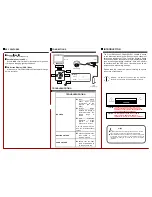
Wiring :
Power
Video
Note
:
●
Please note the camera’s operating temperature is
-
4°F~122°F .
Use of the product outside this range is not recommended.
●
This installation should be made by a qualified service person
and conform to all local codes. Crest Electronics will not be
responsible for damages or injuries as a result of improper
installation
Video
12vdc
CAUTION:
RISK OF ELECTRIC. DO NOT OPEN
MENU
UP
DOWN
RIGHT
LEFT
PRESS
OSD Control
CAUTION:
TO REDUCE THE RISK OF ELECTRIC SHOCK
DO NOT REMOVE COVER OR BACK NO USER
SERVICEABLE PARTS INSIDE. REFER SERVICING
TO OUALIFIED SERVICE PERSONNEL.
CAUTION:
CSA CERTIFIED/UL LISTED CLASS 2 POWER
ADAPTORS MUST BE USED IN ORDER TO
COMPLY WITH ELECTRICAL SAFETY STANDARDS.
NOTICE: For best result, please read this instruction
booklet prior to installing the CCA
-
4810WS
-
21 camera.
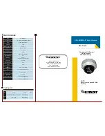
The Crest Electronics CCA
-
4810WS
-
21 camera is based
on the latest high
-
resolution AHD sensor and is capable of
delivering a resolution of 720p. The Wide Dynamic Range
of the sensor allows the camera to capture detailed images
even in challenging lighting conditions. With built in Smart
IR, varifocal lens and OSD menu, this camera can be ad-
justed to suit a wide variety of needs.
Please read this instruction manual carefully to ensure
proper use of the camera.
TROUBLESHOOTING
NO VIDEO
◆
Power
Supply
Check input power
connections at the
terminal (DC input
wires)
◆
Voltage
Range
Measure the voltage at
the terminal block. The
supply
range
is:
12VDC.
◆
Video
Connection
Determine if wiring
polarity
at
“Video
Connector” is correct.
If ok, the problem may be
with the interconnections/
splices.
ROLLING PICTURE
◆
Check to make sure the
coax shield is not
touching “ground”
POOR PICTURE
◆
Ensure that the video
cable is terminated with
75 ohms at each end.


