background image

Index

Chapter 1 Overview

..............................................................................................................................................

1

1.1

Functions and Features

........................................................................................................................

1

1.2

Installation of Main Unit

........................................................................................................................

2

Chapter 2 Main Unit Hardware

............................................................................................................................

3

2.1

Panel functions

.......................................................................................................................................

3

2.2

Interface

...................................................................................................................................................

4

2.2.1

COM Port

.................................................................................................................................

4

2.2.2

RJ45 Internet Cable Production Method

.............................................................................

4

2.2.5

KEYBOARD Interface

............................................................................................................

5

2.3

System Connection Diagram

...............................................................................................................

6

2.4

Operation with Panel Keys

...................................................................................................................

6

2.4.1

LCD Display

.............................................................................................................................

6

2.4.2

Key Light

..................................................................................................................................

6

2.4.3

Menu Setting

...........................................................................................................................

6

2.4.4

Example of Operations

..........................................................................................................

7

2.5

Menu Structure Diagram

.......................................................................................................................

8

Chapter 3 Control Keyboard Operations

...........................................................................................................

9

3.1

Control Keyboard Panel

........................................................................................................................

9

3.2

Control Keyboard Operations

............................................................................................................

10

Chapter 4 Command Set

....................................................................................................................................

11

4.1

Audio/video Switch Command

...........................................................................................................

11

4.1.1

Audio/video Switch Return Command

...............................................................................

12

4.2

Audio Tuning Command

.....................................................................................................................

12

4.2.1

Audio Tuning Return Command

.........................................................................................

12

4.3

Output Resolution Commands

...........................................................................................................

12

4.3.1

Output Resolution Return Commands

..............................................................................

13

4.4

Gamma Value Setting Command

......................................................................................................

14

4.4.1

Gamma Value Setting Return Command

.........................................................................

14

4.5

Contrast Setting Command

................................................................................................................

14

4.5.1

Contrast Setting Return Command

....................................................................................

15

4.6

Detail Enhancement Setting Command

...........................................................................................

15

4.6.1

Detail Enhancement Setting Return Command

...............................................................

15

4.7

Image Color Offset Setting command

..............................................................................................

15

4.7.1

Image Offset Setting Return Command

............................................................................

16

Summary of Contents for CR-SC-390

Page 1: ...al Professional SDI DVI HDMI SDI DVI HDMI Switch Switch Scaler Scaler User User User User User User User User s s s s s s s s Manual Manual Manual Manual Manual Manual Manual Manual V1 1 CREATOR Corporation China ...

Page 2: ...mind the user that the risky uninsulated voltage in the device could caused electric shock to human CE authentication indicates the product is in line with the EU safety regulation and for assurance of safety use SGS Authentication indicates the product has reached the QC standard of the global biggest Swiss universe surveyor This product has acquired the ISO9001 International Quality Authenticati...

Page 3: ...ns with strong interference shielded cable should be used for the input and output of HF signal to improve the anti interference performance of the system Note in Wiring Installation and wiring shouldn t be conducted until external electric power is cut off otherwise electric shock or device damage could happen The product is grounded by the earth lead of the power cable To avoid electric shock th...

Page 4: ...aration of worthless When declaring of worthless please note Explosion of electrolytic capacitor on the circuit board could happen when burning it Please classify and dispose it Don t dispose it into household garbage Please deal it as industrial waste or in accordance with local environmental protection regulation ...

Page 5: ...e Since the date of release any function or relevant parameter alteration will be in supplement command Please refer to the manufacturer or dealers for inquiry CREATOR Electronics own the copyright of the Manual Without permission any unit or person shall not take part or total of the Manual for business purpose The copyright of the Manual is protected by Copyright Law of People s Republic of Chin...

Page 6: ...rd Operations 9 3 1 Control Keyboard Panel 9 3 2 Control Keyboard Operations 10 Chapter 4 Command Set 11 4 1 Audio video Switch Command 11 4 1 1 Audio video Switch Return Command 12 4 2 Audio Tuning Command 12 4 2 1 Audio Tuning Return Command 12 4 3 Output Resolution Commands 12 4 3 1 Output Resolution Return Commands 13 4 4 Gamma Value Setting Command 14 4 4 1 Gamma Value Setting Return Command ...

Page 7: ...ting Command 16 4 9 Network Inquiry Command 17 4 10 Network Interface Default Parameters 17 4 11 Equipment Status Reading Command 17 4 12 Factory Default Setting Restoring Command 18 Chapter 5 Technical Parameters 19 ...

Page 8: ...o video signal Processing 1 way audio video input or output only at one time Compatible with multiple input resolutions CV 480i 480P 576i 576P YC 480i 480P 576i 576P YUV 480i 480P 576i 576P 720P 1080i 1080P VGA 800X600 60Hz 1024X768 60Hz 1280X1024 60Hz 1600X1200 60Hz DVI 800X600 60Hz 1024X768 60Hz 1152X864 75Hz 1280X768 60Hz 1280X960 60Hz 1280X1024 60Hz 1360X768 60Hz 1366X768 60Hz 1440X900 60Hz 16...

Page 9: ...atically saves the current status when there is no other operation in 10 seconds after setting is done Featuring temperature self detecting function with which function the system reads the temperature every 3 seconds and displays on the LCD screen to ensure safety in use Featuring automatic fan on function with which function the fan will be automatically on when the equipment temperature reaches...

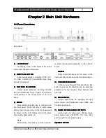
Page 10: ...ng selection key is configured on the front panel Press this key to enter menu setting and the menu key on the front panel will be shown on the LCD display and at the same time the key lights will be on Direction key Use this key to move up down to select the required parameters for the item to be set ENTER ENTER ENTER ENTER Press Enter and move to the menu in the next level from the menu on the f...

Page 11: ... interface offering 2 way RS 232 port for connection with PC or a third party control equipment such as CREATOR CRESTRON AMX control main unit etc 11 11 11 11 Grounding Grounding Grounding Grounding post post post post 12 12 12 12 System System System System power power power power input input input input port port port port System power input is AC 100V 240V 50 60Hz Difference between direction k...

Page 12: ...hite Blue 6 Green 7 White Brown 8 Brown Straight through wiring both ends are connected subject to the standard T568B wiring sequence Crossover wiring with one end connected subject to the T568A wiring sequence and with the other connected subject to the T568B wiring sequence In connection with a network router straight through wiring method will be used in connection with a PC computer crossover ...

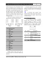
Page 13: ...ng Setting Setting Setting After power connection is properly done the background light of the LCD display will be on at the same time and the system status Loading will be shown on the display After the system is started the main screen will be displayed Menu Menu Menu Menu operation operation operation operation steps steps steps steps may may may may be be be be summarized summarized summarized...

Page 14: ...Step 2 3 and 4 2 4 4 2 4 4 2 4 4 2 4 4 Example Example Example Example of of of of Operations Operations Operations Operations E g Set the output resolution as 1280X1024 60Hz and set contrast to 5 0 1 Press MENU key to enter menu setting and on the LCD display it is shown as follows 2 Press MENU key to enter menu setting and use the key to select the parameter for the OUTPUT Format 3 Press ENTER t...

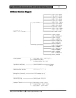
Page 15: ...EATOR CHINA 2011 08 WWW CREATOR1997 COM 8 Professional SDI DVI HDMI Switch Scaler User s Manual 2 5 2 5 2 5 2 5 Menu Menu Menu Menu Structure Structure Structure Structure Diagram Diagram Diagram Diagram ...

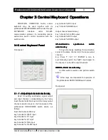
Page 16: ... 3 way output channel selection keys on the front panel of the professional SDI DVI HDMI switch scaler as follows Input channel selection key key 1 stands for YpbPr input key 2 stands for YC input key 3 stands for CV input key 4 stands for VGA input key 5 stands for 3G SDI input key 6 stands for DVI input key 7 stands for HDMI input Output channel selection key key 1 stands for 3G SDI output key 2...

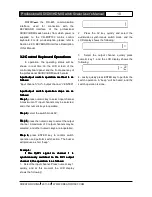
Page 17: ...meric key to select input channel A maximum of 7 input channels may be selected and other numeric keys inoperable Step Step Step Step 2 2 2 2 select the switch mode AV Step Step Step Step 3 3 3 3 press the numeric key to select the output channel A maximum of 3 output channels may be selected and other numeric keys are inoperable Step Step Step Step 4 4 4 4 press ENTER key to confirm switch operat...

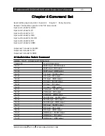
Page 18: ...3 stands for HDMI 4 1 4 1 4 1 4 1 Audio video Audio video Audio video Audio video Switch Switch Switch Switch Command Command Command Command format X Y X Input num Y Output num Command Function Description 1 1 YpbPr input 3G SDI output 1 2 YpbPr input DVI output 1 3 YpbPr input HDMI output 2 1 Y C input 3G SDI output 2 2 Y C input DVI output 2 3 Y C input HDMI output 3 1 CV input 3G SDI output 3 ...

Page 19: ... same audio way Set 1 00 0dB and get the same result as the 2 00 0dB command both meaning YpbPr YC input volume set as 00 0dB 3G SDI and HDMI input audio volume is not adjustable Example Command Function description 1 00 0dB YpbPr YC input volume set as 00 0dB 2 01 0dB YpbPr YC input volume set as 01 0dB 3 05 0dB CV input volume set as 05 0dB 4 20 0dB VGA input volume set as 20 0dB 6 08 0dB DVI in...

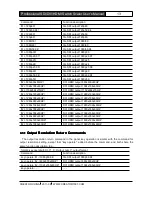
Page 20: ...Z 2 1280x768x60HZ DVI HDMI output 1280x768x60HZ 2 1280x960x60HZ DVI HDMI output 1280x960x60HZ 2 1280x1024x60HZ DVI HDMI output 1280x1024x60HZ 2 1360x768x60HZ DVI HDMI output 1360x768x60HZ 2 1366x768x60HZ DVI HDMI output 1366x768x60HZ 2 1440x900x60HZ DVI HDMI output 1440x900x60HZ 2 1600x1200x60HZ DVI HDMI output 1600x1200x60HZ 2 1920x1080x60HZ DVI HDMI output 1920x1080x60HZ 4 3 1 4 3 1 4 3 1 4 3 1 ...

Page 21: ...e function description e g format key operate gamma X X gamma value range 0 4 1 6 stepping as 0 2 Command Function description key operate gamma 0 6 Set the output gamma value as 0 6 key operate gamma 0 8 Set the output gamma value as 0 8 key operate gamma 1 0 Set the output gamma value as 1 0 key operate 4 5 4 5 4 5 4 5 Contrast Contrast Contrast Contrast Setting Setting Setting Setting Command C...

Page 22: ...ancement Enhancement Enhancement Setting Setting Setting Setting Return Return Return Return Command Command Command Command The detail enhancement setting return command in the panel key operation is similar with the detail enhancement setting command except that key operate is added before the command and both share the same function description E g format key operate DetailLevel X X Detail Leve...

Page 23: ... Offset 0000 green Offset 0000 key operate offset 0010 0020 0030 Set red Offset 0010 blue Offset 0020 green Offset 0030 key operate offset 0400 0500 0600 Set red Offset 0400 blue Offset 0500 green Offset 0600 key operate 4 8 4 8 4 8 4 8 Network Network Network Network Setting Setting Setting Setting Command Command Command Command ASCII command computer to switch scaler Command function return swi...

Page 24: ...12 X13 X14 X15 SUBR GAR Inquire current network gateway number GAR X12 X13 X14 X15 GAR SHAR Inquire current network MAC address number SHAR X12 X13 X14 X15 X16 X17 SHAR 4 10 4 10 4 10 4 10 Network Network Network Network Interface Interface Interface Interface Default Default Default Default Parameters Parameters Parameters Parameters Switch scaler s network port number 5000 Switch scaler s networ...

Page 25: ... Factory Factory Factory Factory Default Default Default Default Setting Setting Setting Setting Restoring Restoring Restoring Restoring Command Command Command Command Restore factory default setting command but not restoring network parameters format Reset Settings Factory default setting value Input DVI Input Format NO INPUT Output DVI DVI Output Format 1024x768x60HZ HDMI Output Format 1024x768...

Page 26: ...C connect or DVI D HDMI A Female connector BNC connect or Signal strength 1V p p Y component video S video complex video 0 7V p p VGA computer signal 0 3V p p separate video S video C HDMI DVI video Min max level analog signal 2V 2V Impedance analog signal 75 Ω HDMI DV I signal 50Ω Echo loss 30dB 5MHz Horizontal frequency response 30 200KHZ Vertical frequency response 20Hz 240Hz VGA video input In...

Page 27: ...tereo audio output Gain 0 dB Frequency response 20 Hz 20 kHz Total Harmonic Distortion Noise 0 05 1 kHz under the rated voltage Signal Noise Ratio S N 58dB Stereo Crosstalk 80dB 1 kHz Common Mode Rejection Ratio CMRR 75dB 20 Hz 20 kHz Signal type Stereo Non end to end audio Impedance input 10 kΩ balance or non balance way of connection output 50 Ω non balance way of connection 100 Ω balance way of...

Page 28: ...HINA 2011 08 WWW CREATOR1997 COM 21 Professional SDI DVI HDMI Switch Scaler User s Manual Storage humidity 10 90 Operating temperature 20 C 70 C Operating humidity 10 70 Housing Dimension 1U Product Weight 1 9kg ...

Page 29: ......

Page 30: ...CREATOR CORPORATION CHINA Copyright by CREATOR Last Revision 08 2011 ...

Reviews: