U ser Manual
TB2I
C O PYRIG H T ©2016 C reatC omm Technology
Figure 7-19 Add W ireless Profile
C lick the Edit button; you can enter the wireless configuration page. The basic settings page as shown
below.
Page 1: ...TB2I 802 11b g n 2 4G Indoor AP Designed for Elevator Security ...
Page 2: ... 8 1 4 U sing Example 9 1 5 Hardware O verview 9 1 6 LED Description 10 2 Installation 11 2 1 C onnections and installation 11 2 2 Restore to Factory Settings 12 2 3 Default Values 12 3 Q uick C onfiguration 13 3 1 Log in 13 3 2 W izard 16 4 Status 19 5 System 21 5 1 System 21 5 2 Administration 23 5 3 LED C onfiguration 25 5 4 Backup U pgrade 25 5 5 Reboot 26 6 Services 27 6 1 C APW AP 27 6 2 SNM...
Page 3: ...32 7 1 Interfaces 32 7 1 1 C ommon C onfiguration 32 7 1 2 DHC P Server 35 7 1 3 Add New Interface 36 7 1 4 Router Mode 38 7 2 W ifi 41 7 2 1 Device C onfiguration 41 7 2 2 Interface C onfiguration 49 7 3 Firewall 52 7 4 VLAN 54 7 5 Ping W atchdog 57 8 Logout 59 9 FAQ 59 ...
Page 4: ...elp the customers quickly be familiar with the devices and use them correctly N o tes This document is to characterize the TB2I series of devices Please read the document carefully before setting up devices Any damage which is caused by inappropriate use will not be covered under the warranty D efinitio ns Table 2 Definitions No Items Description 1 TB2I Specifically for elevator wireless video tra...
Page 5: ...int 4 Station C lient W IFI station that can be associated to an access point 5 C PE C ustomer premises equipment it is any terminal and associated equipment located at a subscriber s premises and connected with a carrier s telecommunication channel at the demarcation point ...
Page 6: ...VTrans technology TB2I devices is embedded with VTrans technology including TDMA 20M 40MHz bandwidth intelligent rate control Auto AC K Time out adjust It makes the device have longer transmission distance higher throughput and better point to multi point performance 4 Embedded hardware watchdog TB2I is embedded with hardware watchdog which is used to monitor the working status of the device O nce...
Page 7: ...e Sensitivity 72dBm 65Mbps 97dBm 1Mbps O peration Frequency 11n 300Mbps HT40 130 HT20 11g 54Mbps H a r d w a r e Power supply 48V PO E or 12V DC Interface 3 10 100M Base TX C at 5 5E RJ 45 ports O peration Temperature 30 65 Storage Temperature 40 85 O peration Humidity 5 95 RH Dimensions 150 150 31 6mm S o f t w a r e Application scenarios Elevator C ar Elevator Room Encryption W PA PSK W PA2 PSK ...
Page 8: ...ligent rate control Auto AC K Time out adjust TDMA solves the problems of hidden node problem in the 802 11 network thus having better long distance and PTMP performance Support point to point point to multipoint connection U nique antenna RF amplifier and low noise receiver to ensure long distance video transmission W eb based working scenario selection makes the installation and setting much eas...
Page 9: ... updates Backhaul data networks can rely on existing properties or assembling outdoor wireless device Figure 1 1 TB2I U sing Example 1 5 Hardware O verview Hardware information of TB2I is described in the following Table Table 1 2 Hardware Information Hardware Specifications C PU Baseband Radio Atheros Q C A9531 Memory 64MB DRAM 8MB Flash Physical Interface 3 10 100M Base TX C at 5 5E RJ 45 Ports ...
Page 10: ...first left LED indicator for the LAN the second from the left for the W LAN indicator light the middle three signal strength indicator as specified in the following Table Figure 1 2 LED Table 1 3 LED Information LED C olor Status LAN Yellow The light indicates there is an external device connects to the LAN port which is the LAN1 port of TB2I W LAN G reen The light indicates that the wireless TB2I...
Page 11: ...e wireless signal level is high O nly yellow and red lights on indicating signal level is medium O nly red light on indicating that the signal is weak or no signal Yellow G reen 2 Installation 2 1 C onnections and installation The installation of TB2I as shown in the following figure Figure 2 1 C onnections 1 TB2I Device 2 PO E power adaptor 3 Mount Bracket ...
Page 12: ... You can also use your own DC 12V power supply for the device 2 2 Restore to Factory Settings In some cases users can restore the device to factory settings Push the reset button for 5 10 seconds and wait for 2 3 minutes The device will restore to factory settings Figure 2 2 Reset 2 3 Default Values There are two TB2I devices TB2I T and TB2I R a twin pack They can be used directly without debuggin...
Page 13: ...on W PA2 PSK Key 1234567890abc W PA2 PSK Key 1234567890abc Network mode Bridge Bridge 3 Q uick C onfiguration 3 1 Log in To log in the TB2I device you need to configure the TC P IP of your computer first as the following steps 1 Right click Local Area C onnection icon of your computer and click properties then click C ontinue the Local Area C onnection Properties dialog box appears as shown below ...
Page 14: ... ser Manual TB2I C O PYRIG HT 2016 C reatC omm Technology Figure 3 1 Local Area C onnection Properties 2 Select Internet Protocol TC P IP and click Properties button and the following dialog box appears ...
Page 15: ...here can be a number between 1 255 but not 36 or 35 since the TB2I T default IP address is 192 168 1 35 and the TB2I R default IP address is 192 168 1 36 4 Input the default IP 192 168 1 36 or 192 168 1 35 into the address bar of your web browser click Enter 5 Input the user name and password default is root admin the you can log in to the web configuration menu of the TB2I device ...
Page 16: ...uickly configure TB2I according to the following steps through the wizard in this chapter 1 The first page shown after log in is the Status page which indicates the working status current setting software version and other information of the TB2I device U ser can switch to other pages by clicking the main menus ...
Page 17: ...U ser Manual TB2I C O PYRIG HT 2016 C reatC omm Technology ...
Page 18: ...s to configure the device to Router mode please refer to chapter 7 Note If there are several TB2I devices connected in the Point to Point or Point to Multi Point topologies they must be configured to different IP address to avoid conflicts Figure 3 5 W izard TB2I T Elevator C ar AP mode in this scenario mode TB2I will be set to AP mode it can be connected to a client device W hen you close the TDM...
Page 19: ...o or data if there are other TB2I equipment within 500 meters you should change SSID to different one in order to avoid connection confusion please refer to chapter 7 to see how to modify the SSID 3 C lick Save Apply button the device will reboot and apply your configuration Figure 3 7 C omplete wizard settings 4 Status The status page is the first page after logging in the page displays the curre...
Page 20: ...U ser Manual TB2I C O PYRIG HT 2016 C reatC omm Technology ...
Page 21: ...vice system current process and its status information please do not click Hang U p Terminate Kill without the guidance of network manager so as to avoid unnecessary trouble Real time G raphs display the real time load traffic and link information of the device 5 System System page includes System Administration Software Startup Scheduled Tasks LED C onfiguration Backup Flash Firmware and Reboot s...
Page 22: ... status of the device Host name is corresponding to the Router Name of the status page users can change it according to their own needs as shown in the figure Figure 5 1 System Properties G eneral Settings Logging W hen Syslog is enabled and the System Log server s IP is also set here the log information will be output to the Syslog server automatically Figure 5 2 System Properties Logging ...
Page 23: ...d Style Time Synchronization when the device can surf the Internet you can enable the NTP client and fill in the NTP server candidates TB2I will get time automatically from the NTP server and displayed in the status page At this point you can also tick the Provide NTP server and make the device as a NTP server for other devices connected to the TB2I to acquire time Figure 5 4 System Properties Tim...
Page 24: ... P server Here you can change the default SSH parameters Figure 5 6 SSH Note after saving the configuration of administration page the device will automatically close telnet access the user can login the device through more secure SSH System Software Startup and Scheduled Tasks pages it is not recommended to operating just keep the default configuration ...
Page 25: ... red LED 95 1dBm yellow 71 1dBm green 56 1dBm W hen the signal strength is higher than 95dB and below 71dBm red light when the signal strength is higher than 71dB and below 56dBm both red and yellow light when the signal strength is higher than 56dBm all the 3 LEDs light 5 4 Backup U pgrade System Backup Flash Firmware page is very simple to use It is divided into the following 2 parts Backup Rest...
Page 26: ... pload a sysupgrade compatible image here to replace the running firmware C heck Keep settings to retain the current configuration requires an O penW rt compatible firmware image Figure 5 9 Flash new firmware image 5 5 Reboot C lick Perform reboot to reboot the operating system of your device Figure 5 10 Reboot ...
Page 27: ... to their own interface configuration Location the location of the device on the AC it can be modified in the AC according to your needs Discovery mode choosing how to find the IP address of AC W hen you choose Auto AC IP can be automatically discovered by the device when you choose manual you need to fill in AC IP address After C APW AP feature is enabled click on the save application button the ...
Page 28: ... ser Manual TB2I C O PYRIG HT 2016 C reatC omm Technology Figure 6 2 C APW AP Settings 6 2 SNMP SNMP W hen SNMP is enabled you can check the working condition and information of the device by a SNMP tool ...
Page 29: ... HT 2016 C reatC omm Technology Figure 6 3 SNMP You can configure the SNMP parameters in Basic Settings part C heck SNMP Enable and fill in Location Mail G roup then you can manage the device through a SNMP tool in your computer ...
Page 30: ...ual TB2I C O PYRIG HT 2016 C reatC omm Technology Figure 6 4 Basic Settings The device supports a higher level of SNMP protocol you can choose to enable SNMPv3 with the corresponding SNMP management tools to use ...
Page 31: ...nology Figure 6 5 SNMPv3 Settings The device also supports trigger trap information you can choose to enable Trap fill in the trap server IP then you will receive Trap information through the SNMP management tool in your computer Figure 6 6 Trap Settings ...
Page 32: ...introduction of the Interface W ifi Diagnostics Firewall VLAN Ping W atchdog 7 1 Interfaces 7 1 1C ommon C onfiguration O pen the network interface page you ll see the overview of the current interface Figure 7 1 Interfaces C lick Edit button you will enter the Interfaces LAN page O n this page you can configure the network interfaces You can bridge several interfaces by ticking the bridge interfa...
Page 33: ...tocol the interface access IP address options it divided into static address DHC P client to obtain the IP dynamically and a variety of other ways If you set a static IP you need to set the IP subnet mask etc when set to DHC P client the device can obtain IP from DHC P server automatically ...
Page 34: ...e you can modify the current interface configuration which contains the wired interface and wireless interface Figure 7 3 Physical Settings Bridge interfaces creates a bridge over specified interface s unchecking the Bridge interfaces and you could only choose one interface Enable STP Enables the Spanning Tree Protocol on this bridge Interface Ethernet adapter eth0 corresponds to the PO E power su...
Page 35: ...chnology the create field to define a new zone and attach the interface to it please refer to the Manual Section 7 3 firewall Figure 7 4 Firewall Settings 7 1 2DHC P Server Drop down the interface page you can see the basic settings of the DHC P server ...
Page 36: ...e 7 5 DHC P Server DHC P Assign IP address to client device such as phones laptops etc A device should enable DHC P client mode to get IP automatically 7 1 3Add New Interface C lick on the Add new interface button to add a new interface Figure 7 6 Add new interface ...
Page 37: ...rnet adapter eth1 interface all of the configuration in this page can be modified again in the subsequent pages Figure 7 7 C reate Interface C lick Submit will enter the new LAN2 interface configuration page This page can be configured for all the existing interfaces as shown below you can still see the original LAN interface ...
Page 38: ... Routing mode TB2I is equivalent to a router it has a W AN port and LAN port You should select an interface which needs to be removed from the default LAN interface for the W AN interface configuration Below we will set eth1 port to W AN as an example introduces the configuration of the W AN Please refer to the manual 7 1 1 Ethernet adapter eth1 removed from the LAN interface ...
Page 39: ...the name of the new interface such as ETH1 you can choose a static address for the new interface protocol all of the current page configuration can be modified in the subsequent page Figure 7 10 Router Interface C lick submit Into the newly created interface configuration page fill in the IPv4 address which should be different with LAN segments such as 192 168 2 35 ...
Page 40: ...address and W AN IP address are in the same network In general setup the firewall settings page select the default wan firewall zone after saving the application you will see ETH1 is set to the W AN zone then routing mode setup is complete eth1 port is set for the W AN port Firewall rules modify please refer to the chapter 7 3 firewall chapters ...
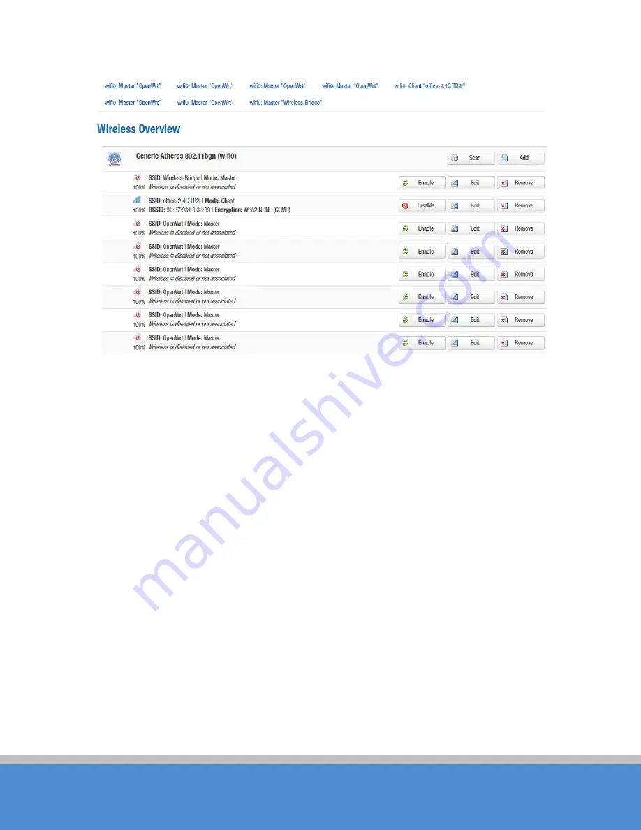
Page 41: ... The Device C onfiguration section covers physical settings of the radio hardware such as channel transmit power or antenna selection which is shared among all defined wireless networks if the radio hardware is multi SSID capable O pen the Network W ifi page you will see the current wireless profile and the information of associated stations ...
Page 42: ...B2I C O PYRIG HT 2016 C reatC omm Technology Figure 7 13 W ireless O verview The device can scan the SSID nearby you can connect to the corresponding wireless network according to your needs Figure 7 14 Scanning SSID ...
Page 43: ... Join Network it will appear the following tips as shown below and if you check Replace the wireless configuration click on the confirmation will cover all current wireless template settings please choose carefully Figure 7 15 Join Network 1 Here we uncheck the Replace wireless configuration click Submit it will appear the following page below ...
Page 44: ...ual TB2I C O PYRIG HT 2016 C reatC omm Technology Figure 7 16 Join Network 2 C lick Save Apply wait a moment and then Turn to Network W ifi page you will see the office 2 4G TB2I on the Associated Stations list ...
Page 45: ...ere is a client mode wireless profile in the 8 profiles click on Join Network will appear as follows Figure 7 18 Join Network 4 C lick the Add button to add more wireless profiles the device can add up to eight wireless profiles and the device can only have one client mode profile you can choose to enable or disable the added wireless profiles ...
Page 46: ...U ser Manual TB2I C O PYRIG HT 2016 C reatC omm Technology Figure 7 19 Add W ireless Profile C lick the Edit button you can enter the wireless configuration page The basic settings page as shown below ...
Page 47: ...ime Transmit Power The device output power W hen the output power is increased the signal distance and signal strength will be improved Mode You can keep the default 802 11g n mode to guarantee optimal transmission rate HT Mode C hannel width selection the device supports 20 40 40 MHz bandwidth In general the wider the bandwidth is the greater the data throughput rate Max Transmission Rate it can ...
Page 48: ...vice works at the channels only permitted in the particular country W hen you set C ompliance Test mode the frequency will extend to 2312 2732MHz Aggregation It enables several data frames of 802 11 to be aggregated and transmitted out thus improve the throughput The larger the set value the higher the throughput VAP Isolation The device supports multiple VAP if this feature is enabled and when th...
Page 49: ...adjust the wireless parameters to achieve the best link quality To use the TDMA the user needs to enable TDMA mode in the AP device and set a priority level in the station device W hen several stations are connected to one AP different clients demand different throughput If the client demands higher throughput its priority level can be set to High otherwise set to Low W hen the client demands the ...
Page 50: ...DS feature to link multiple APs in a network all associated stations from any AP can communicate with each other like in ad hoc mode C lient W DS means this device is a client in W DS mode Access Point W DS Use W DS feature to link multiple APs in a network all associated stations from any AP can communicate with each other like in ad hoc mode W DS AP means this device is an AP in W DS mode Networ...
Page 51: ...st be set to the same encryption Figure 7 24 Interface C onfiguration MAC Address MAC Address Filter used to control communication between the device and other devices Allow listed only only the list of devices that are allowed to connect to the access point and the other device does not allow access to the access point Allow all except listed allow the device to connect to the access point outsid...
Page 52: ...Settings Station Isolation Enable this function STA can t communicate with each other Max Station Limit You can set the number of STA that connect to AP 7 3 Firewall The firewall creates zones over your network interfaces to control network traffic flow The default settings of firewall zone as shown below ...
Page 53: ...d other areas can be modified For example click on Edit button of LAN zone as shown below this section defines common properties of lan The input and output options set the default policies for traffic entering and leaving this zone while the forward option describes the policy for forwarded traffic between different networks within the zone A covered network specifies which available networks are...
Page 54: ...targeted at lan The forwarding rule is unidirectional e g a forward from lan to wan does not imply a permission to forward from wan to lan as well Figure 7 28 Inter Zone Forwarding 7 4 VLAN VLANs are often used to separate different network segments The VLAN function allows user to create multiple virtual local area network As shown in figure we add a VLAN on port ath0 wireless network port The VL...
Page 55: ...ings Bridge function is needed to use together with VLAN As show below we add VLAN 10 on port eth0 and ath0 they are eth0 10 and ath0 10 Figure 7 30 Add VLAN ID Then we create a new interface and put eth0 10 and ath0 10 into the same bridge in Network Interfaces page as shown below ...
Page 56: ...terfaces The packets from eth0 10 or ath0 10 will be added a VLAN label which ID is 10 That requires the opposite wireless connection side must support VLAN 10 the device which connects with eth0 is also need to support VLAN 10 such as a VLAN Switch C ommon connection mode as shown below ...
Page 57: ...e to continuously ping a user defined IP address for example it can be the IP address of the AP the C lient is connecting to If it is unable to ping under the user defined constraints the device will automatically reboot It is highly recommended that users enable this feature at the side of Station and disable this feature at the side of Access Point ...
Page 58: ... seconds between the pings requests are sent by the Ping W atchdog Start up Delay specify initial time delay in seconds until first ping request is sent by the Ping W atchdog Ping Failure Specify the number of ping replies If the specified number of ping replies is not received continuously the Ping W atchdog will reboot the device Note If users want to modify the parameters of Ping W atchdog plea...
Page 59: ... typing the default IP address 192 168 1 36 192 168 1 35 3 How to modify the IP address of the device Please open the device page followed by click Network interfaces select Edit button of the LAN interface C ommon C onfiguration G eneral Setup IPv4 address here you can set the IP address according to your own needs But you should ensure the IP you edit is different with other devices so as to avo...
Page 60: ...e Apply button then click G eneral Setup modify the basic channel and save the application Please refer to manual 7 2 1 Device configuration section Multiple devices IP conflict with each other you need to modify the IP address followed by click Network Interfaces G eneral Setup IPv4 address Please reference manual 7 1 1 C ommon C onfiguration section 6 Mobile phones and computers cannot connect t...
Page 61: ...8 I don t want anyone to connect to my device Modify the password of the access point AP Followed by click Network W ifi select corresponding SSID and click Edit interface configuration W ireless Security For details please reference manual 7 2 2 interface configuration section To hide the ESSID of the AP Followed by click Network W ifi select corresponding SSID and click Edit button interface con...