background image

7

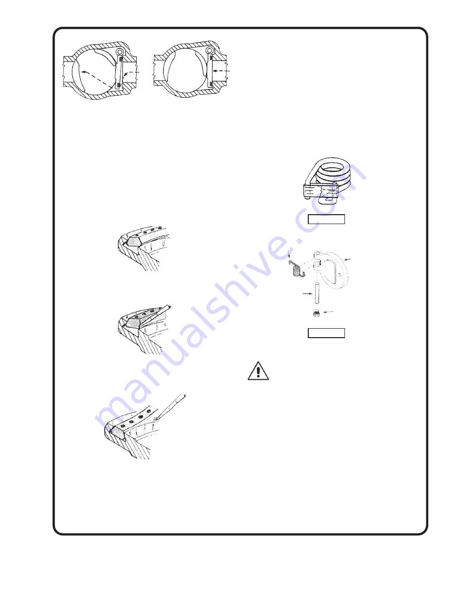
REPAIR CLAPPER SEAL:

HVAC TDV valves are equipped with Buna-N clapper 

seals. If the clapper seal is damaged, they can be 

replaced by removing the clapper and installing a new 

seal (see steps 1-3 below).

Step 1

Place the outer edge of the seal into the clapper groove 

as shown.

Step 2

Using a blunt screwdriver, force the inside lower edge of 

the seal into the clapper groove.

Step 3

As you work the seal in, maintain force on the portion 

of the seal that has been installed. This will prevent 

elongation and excessive build-up of closing portion.

REPLACEMENT PROCEDURE:

1. 

Position clapper firmly against the seat face.

2. 

Pre-load spring and bind using filament tape (see 

Figure 4a)

3. Take the clapper pin with the extension screw and 

insert the pin into the spring and support hangers (see 

Figure 4b)

4. 

When holding the clapper firmly against the seat, the 

clapper pin must move freely into position.

5. Remove the extension screw, replace the clapper pin 

plug, and cut the filament tape to free the spring.

6. Check the clapper for free movement by opening and 

closing the clapper by hand.

7. If movement is free, complete the valve assembly.

6. WIRING

WARNING: DO NOT START PUMP UNTIL IT 

HAS BEEN FILLED WITH WATER.

1. Motor wiring should conform to national and local

    electrical codes.

2. Use wire of adequate size to prevent voltage drop.

3. Pump should be on a branch or separate circuit,

    fused or circuit breaker, protected, with a manual

    disconnect.

4. Connect the electrical supply from the switch to the

    motor terminals, following the wiring diagram on

    the motor nameplate or terminal cover plate. 


NOTE:

 be sure that the connections to the motor

    terminals correspond with the voltage to be 

    applied. (See Chart)

Check wiring and fuse charts before connecting wires to 

service line. Make sure the voltage and frequency of the 

electrical current supply agrees with that stamped on the 

motor nameplate. If in doubt, check with power company.

Closed Position

As the plug is rotated 

toward the closed position, 

the downstream part 

closes first. This equalizes 

the Pressure so the 

clapper closes with little 

resistance.

Positive Seal Closure

Final closing is 

accomplished by the plug 

camming against the back 

of the clapper.

Figure 4a

Spring

Figure 4b

Clapper Pin Plug

Clapper

Clapper Pin

Summary of Contents for WEINMAN 100

Page 1: ...stant product improvement program product changes may occur As such Crane Pumps Systems reserves the right to change product without prior written notification 420 Third Street 83 West Drive Brampton Piqua Ohio 45356 Ontario Canada L6T 2J6 Phone 937 778 8947 Phone 905 457 6223 Fax 937 773 7157 Fax 905 457 2650 www cranepumps com Form No 096882 Rev H Sections 320 100 200 300 and 500 ...

Page 2: ...arge openings DO NOT insert fingers in pump with power connected Always wear eye protection when working on pumps Make sure lifting handles are securely fastened each time before lifting DO NOT operate pump without safety devices in place Always replace safety devices that have been removed during service or repair Secure the pump in its operating position so it can not tip over fall or slide DO N...

Page 3: ...rvice Center check your Weinman representative or Crane Pumps Systems Service Department in Piqua Ohio telephone 937 778 8947 or Crane Pumps Systems Canada Inc Brampton Ontario 905 457 6223 B INSTALLATION 1 FOUNDATION The pump foundation should be sufficiently substantial to form a level rigid support for the combined weight of the pump and driver and maintain alignment of the installed unit Found...

Page 4: ...g The unit will be in angular alignment when the coupling faces are exactly the same distance apart at all points See Figure 3 Parallel alignment check is made by placing a straight edge across both coupling rims at the top bottom and at both sides The unit will be in parallel alignment when the straight edge rests evenly on the coupling rim at all positions Allowance may be necessary for temperat...

Page 5: ...any high points in the line which will form air pockets the pump will not operate properly 3 If conditions require the use of a foot valve and strainer the flow area of the foot valve should be from 1 1 2 to 2 times the area of the suction pipe and the strainer should have a free opening area equal to 3 to 4 times the area of suction pipe Otherwise excessive frictional loss will result 4 If a gate...

Page 6: ...irable that the dis charge line be provided with a flexible connection TDV DESIGN AND OPERATION The principle of operation for the TDV valve is extremely simple When in the open position the clapper swings out of the flow If the flow stops the spring allows the clapper to close When closing the valve a final bumping action with a wrench gives the final positive seal closure TDV MAINTENANCE The TDV...

Page 7: ...vement by opening and closing the clapper by hand 7 If movement is free complete the valve assembly 6 WIRING WARNING DO NOT START PUMP UNTIL IT HAS BEEN FILLED WITH WATER 1 Motor wiring should conform to national and local electrical codes 2 Use wire of adequate size to prevent voltage drop 3 Pump should be on a branch or separate circuit fused or circuit breaker protected with a manual disconnect...

Page 8: ...8 PIPING Right Wrong FIGURE 5 ...

Page 9: ... priming is accomplished by completely filling the suction piping and pump casing with the liquid to be pumped This can be done by removing the air vent valve or plug at the top of the pump casing and inserting a pipe nipple in the orifice with an appropriate increaser to accommodate a hose connection A priming line can also be inserted in the discharge piping between the check valve and the pump ...

Page 10: ...ould be clean and polished smooth Slide seal body on shaft washer end first and seat firmly A sleeve as shown in Fig 6 will facilitate this operation and prevent the rubber driving ring from pulling out of place as the seal body is slid along the shaft Assembly of impeller automatically sets seal in proper position Make sure at all times and particularly before final assembly that both sealing fac...

Page 11: ...diment When installing in pond or lake support the suction line so that it will be submerged in water but nut imbedded in mud or sediment A strainer with greater screen area may be required d Add sufficient pipe to keep the submerged end well below the water surface e If caused by suction pipe friction increase the size of the pipe otherwise move the pump closer to the water level f Order replacem...

Page 12: ...A RETURNED GOODS AUTHORIZATION CONTACT YOUR LOCAL CRANE PUMPS SYSTEMS INC DISTRIBUTOR Products Returned Must Be Cleaned Sanitized Or Decontaminated As Necessary Prior To Shipment To Insure That Employees Will Not Be Exposed To Health Hazards In Handling Said Material All Applicable Laws And Regulations Shall Apply IMPORTANT WARRANTY REGISTRATION Your product is covered by the enclosed Warranty If ...

Reviews: