


completely stopped. The engine ignition lever
should be set to »0« position so that the engine
cannot be started accidentally. In addition, the
gas lever must be in »Stop« position.
13. Never leave the machine unattended while the
engine is running.
14. Never run the engine in closed rooms: Danger of
intoxication!
15. Do not place hands or feet under the suction
nozzle or near rotating parts.
16. The area to be vacuumed should be clear of sto-
nes, wires etc. which could be picked up by the
rotor and flung in any direction, causing injury to
the operator or bystanders.
17. Do not vacuum materials that could clog the
rotor.
18. Always switch off the engine and wait until the
rotor has stopped completely before doing the
following:
1. Removing the foliage bag or clearing a block-
age in the infeed channel, or
2. Removing the suction nozzle or clearing a
blockage in the suction nozzle
3. Repairs, adjustments or removal of foreign
items.
19. When using the foliage vacuum as a foliage blo-
wer, the protective cover at the rotor inlet has to
be properly fitted. The blower should not be poin-
ted at persons.
20. The foliage bag should be cleaned at regular
intervals to guarantee proper filter performance.
21. Never empty the foliage bag when the engine is
running.
22. Never replace the suction nozzle or suction tube
while the engine is running.
23. Use only manufacturer’s approved accessories
and original spare parts.
24. Only qualified personnel should be allowed to
carry out repairs and maintenance.
4. Operation
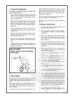
As mentioned in section 2 the machine is pre-assem-
bled in the works with the exception of the foliage bag
and suction nozzle.
Fit the suction nozzle (3) and foliage bag (8) as shown
in Fig. 1, paying particular attention to the adjustment
of the Bowden cable (25/32) for the switch bar (31) to
prevent slipping of the engine clutch.
The engine is started by means of a recoil starter,
after first having set the ignition lever to »1« and the
gas lever to »start«. For further information, please
refer to the attached instructions of Honda.
The suction power of the rotor (51) is largely depen-
dent upon the height of the suction nozzle, (3) i.e. the
heavier the material to be picked up, the lower it
should be (right down for moist foliage and higher for
dry foliage).
The front and sides of the foliage bag (8) are fitted
with air-permeable filter material. The upper and rear
surface is less permeable out of consideration for the
operator. When large volumes of air are sucked in, i.e.
with a high position of the suction nozzle, additional fil-
ter surfaces can be created by opening the zips on
the right and left.
The foliage bag is full when the machine tends to tip
backwards, lifting the suction nozzle (3) at the front. In
this case the foliage bag (8) should be emptied by
opening the circumferential zip on the back and emp-
tying it by means of the handle provided on the front
side. The opened part of the bag can be folded up out
of the way by means of a Velcro fastener.
Model LS 3500 has to be pushed over the surfaces to
be cleaned. Model LS 5000/LS 5000 H has a self-pro-
pelled drive which is started by means of the switch
bar (31) on the steering handle. Model LS 5000/LS
5000 H features free-wheeling ball bearings for curve
negotiating ability (38).
How to convert the foliage vaccum (3) into a foliage
blower: Unscrew the suction nozzle and the outlet
connecting piece (7). To cover the two openings, fit
the guard (59) supplied as an accessory. Then pull
back the locking plate (24) at the back to release the
lock and turn the rotor body (51) by approx. 90 deg.
(in counter-clockwise direction seen from the front of
the machine).
Caution: rotation in the wrong direction might
damage cable to contact switch (5).
5. Maintenance Instructions
Strong vibrations arise when vac is on. It is there-
fore necessary to check screw tightness after a
few working hours.
Always set the ignition lever of the engine to »0« prior
to carrying out maintenance or repairs. To clean the
foliage bag (8), release the bag from the outlet (7)
connecting piece and undo the retaining straps. The
filter material of the foliage bag will eventually become
clogged. In this case, turn the bag inside out and
shake it out completely, or wash foliage bag in a water
bath or by rinsing with water; industrial cleaning is
also possible.
From time to time the suction nozzle (3) at the front of
the machine should be dismantled and the blower
rotor (14) inspected for damage caused by foreign
items.
Check the air pressure of the rear wheels (36/46a+b)
occasionally according to the technical data.
The drive engine should be serviced as described in
Summary of Contents for LS3500
Page 5: ...9 Spare Parts Drawing ...