background image

Summary of Contents for EZ3 917.273042

Page 1: ...042 Safety Assembly Operation Maintenance Repair Parts CAUTION Read and follow all Safety Rules and Instructions before operating this equip ment For answers to your questions about this product Call 1 800 659 5917 Sears Craftsman Help Une 5 am 5 pm Mon Sat Sears Roebuck and Co Hoffman Estates IL 60179 ...

Page 2: ...nty service on your Craftsman ridingequipment is available at no charge for 30 days from the date of purchase Please contact your nearest service center After 30 days from the date of pumhase warranty service is available by taking your Craftsman ridingequip ment to your nearest Sears Service Center In home warranty sew mewill still be avail able after 30 days from the date of purchase but a stand...

Page 3: ...dge of a cliff or ditch or if an edge caves in Do _t mow on wet grass Reduced traction could cause sliding Do nottry to stabilize the machine by puttingyour foot on the ground Do not use grass catcher on steep slopes CHILDREN Tragic accidents can occur if the operator is not alert tO the presence of children Children are often attracted to the machine and the mowing activity Never assume that chil...

Page 4: ...and turn machine off if children enter the area Before and when backing look behind and down for small children Mow up and down slopes 15 Max not across Remove obstacles such as rocks tree limbs etc Watch for holes ruts or bumps Uneven terrain could overturn the machine Tall grass can hide obstacles Use slow speed Choose a low gear so that you will not have to stop or shift while on the slope Avoi...

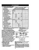
Page 5: ...mble and maintain your tractor properly Always observe the SAFETY RULES MAINTENANCE AGREEMENT A Sears Maintenance Agreement is avail able on this product Contact your nearest Sears store for details CUSTOMER RESPONSIBILITIES Read and observe the safety rules Follow a regular schedule in maintain ing caring for and using your tractor Follow the instructions under Mainte nance and Storage sections o...

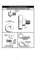
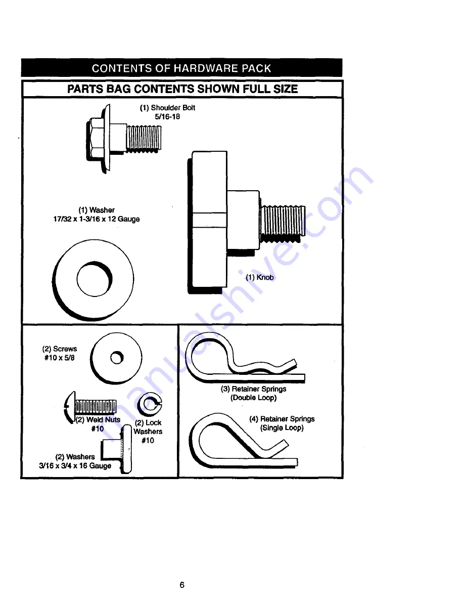
Page 6: ...WN FULL SIZE 1 Shoulder Bolt 5 16 18 1 Washer 17 32 x 1 3 16 x 12 Gauge 1 Knob 2 Screws 10 x 5 8 i A 2 Weld Nuts 2 Lock 1_ Washers i 1o 2 Washers L_ 3 16 x 3 4 x 16 Gauge _ 3 Retainer Springs Double Loop 4 Retainer Springs 6 ...

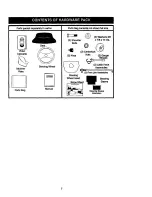
Page 7: ...ssette Steering Wheel Mulcher Plate Parts Bag __ Manual _ 2 Washers 3 8 2 Shoulder x 718 x 14 Ga Bolts 2 Centerlock 2 Keys Nuts 2 Gauge Wheels r 1 F _ _ _ 2 Latch Hook _ Assemblies t _ z_ 2 Front LinkAseemblie s Steering Wheel Insert Steering Slope Sheet Sleeve Steering Sleeve Extension 7 ...

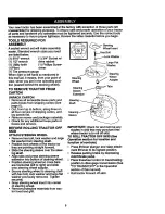
Page 8: ...EEL Remove hex bolt lock washer and large fiat washer from steering shaft Position front wheels of the tractor so they are pointing straight forward Slide the steering sleeve over the steer Jn_ shaft Align tabs and press steering sleeve extension into bottom of steering wheel Position steering wheel so cross bars are horizontal left to right and slide onto steering wheel adapter Secure steering wh...

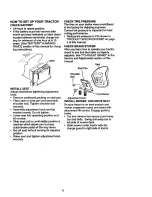
Page 9: ...n Get off seat without moving its adjusted position Raise seat and tighten adjustment knob securelv CHECK TIRE PRESSURE The tires on your tractor were overinflated at the factory for shipping purposes Correct tire pressure is important for best cutting performance Reduce tire pressure to PSI shown in PRODUCT SPECIFICATIONS on page 5 of this manual CHECK BRAKE SYSTEM After you leam how to operate y...

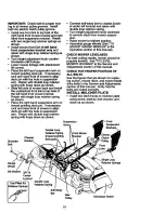
Page 10: ... align deck pin with the hole in suspension arm Retain with double loop retainer spring with loops down as shown Chassis Shoulder Bracket BoR Connect anti sway bar to chassis brack et under left footrest and retain with double loop retainer spring Tum height adjustment knob clockwise to remove slack from mower suspen sion Raise mower to highest position Assemble gauge wheels See TO ADJUST GAUGE WH...

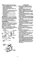
Page 11: ...ose parts in carton Battery is properly prepared and charged Minimum 1 hour at 6 amps Seat is adjusted comfortably and tight ened securely All tires are properly inflated For ship ping purposes the tires were overinflat ed at the factory Be sure mower deck is properly leveled side to side front to rear for best cutting results Tires must be properly inflated for leveling Check mower and drive belt...

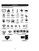
Page 12: ...REVERSE FORWARD FAST SLOW WARNING FUEL CHOKE MOWER HEIGHT PARKING BRAKE UNLOCKED MOWER LIFT LOCKED N H L ATTACHMENT REVERSE NEUTRAL HIGH LOW PARKING BRAKE CLUTCH ENGAGED ATTACHMENT KEEP AREA CLEAR SLOPE HAZARDS IGNmON CLUTCH DISENGAGED SEE SAFETY RULES SECTION DANGER KEEP HANDS AND FEET AWAY FREE WHEEL Automatic Modelsone 12 ...

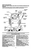
Page 13: ...tor LIGHT SWITCH Tums the headlights on and off THROTTLE CONTROL Used to control engine speed CLUTCH BRAKE PEDAL Used for declutching and braking the tractor and starting the engine CHOKE CONTROL Used when starting a cold engine HEIGHT ADJUSTMENT KNOB Used to adjust the mower cutting height IGNIT4ON SWITCH Used for starting and stopping the engine ATTACHMENT LIFT LEVER Used to raise and lower the ...

Page 14: ...d allowing engine to idle before stopping may cause engine to backfire Tum ignitionkey to OFF position and remove key Always remove key when leaving tractor to prevent unauthorized use Never use choke to stop engine IMPORTANT Leaving the ignitionswitch in any positionother than OFF will cause the battery to be discharged dead NOTE Under certain conditionswhen tractor is standing idle with the engi...

Page 15: ...e attachment clutch engaged _vill shut off the engine Select desired height of cut Lower mower with attachment lift con trol Start mower blades by engaging attach ment clutch control TO STOP MOWER BLADES disen _gA e attachment clutch control UTION Do not operate the mower without either the entire grass catcher on mowers so equipped or the discharge guard in place TO OPERATE ON HILLS _CAUTION Do n...

Page 16: ...rade gasoline to help insure good _dNAweather starting RNING Expedence indicates that alcohol blended fuels called gasohol or using ethanol or methanol can attract moisture which leads to separation and formation of acids dudng storage Acidic gas can damage the fuel system of an engine while in storage To avoid engine problems the fuel system should be emp tied before storage of 30 days or longer ...

Page 17: ...ACAUTION Never engage or disen gage freewheel lever while the engine is running To ensure proper operation and perfor mance it is recommended that the trans mission be purged before operating tractor for the first time This procedure will remove any trapped air inside the trans mission which may have developed during shippingof your tractor IMPORTANT Should our transmission require removal for ser...

Page 18: ...en operating attachments select a ground speed that will suit the terrain and give best performance of the at tachm_LnLbeing used MULCHING MOWING TIPS IMPORTANT For best performance keep mower housing free of built up grass and trash Clean after each use The special mulching blade will recut the grass clippings many times and reduce them in size so that as they fall onto the lawn they will dispers...

Page 19: ...ms that have been subjected to operator eSpindle _N_ _ _ _ S abuse or negligence To receive full value pindle Zerk from the warranty operator must maintain eFmnt_ _ _ eFront tractor as instructed in this manual Some Wheel U_JI t r W Wheel adjustments will need to be made pedodi Bearing A _ _ L Bearing cally to properly maintain your tractor Zerk _ _ _1 _ Zerk All adjustn_ents in the Service and eS...

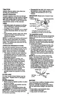
Page 20: ...lades Remove hex bolt lock washer and flat washer securing blade Install new or rasharpened blade with trailirlt_ edge up towards deck as shown IMPORTANT To ensure proper assembly center hole in blade must align with star Reassemble hex bolt lock washer and flat washer in exact order as shown Tighten bolt securely 27 35 Ft Lbs torque IMPORTANT Blade bolt is Grade 8 heat treated Trailing Ec_gsUp Ma...

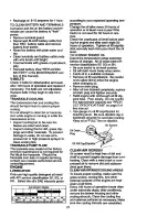
Page 21: ...L CHANGE according to your expected operating tem perature Change the oil after every 50 hours of operation or at least once a year if the tractor is not used for 50 hours in one year Check the crankcase oil level before start ing the engine and after each eight 8 hours of operation Tighten oil fill cap dip stick securely each time you check the oil level TO CHANGE ENGINE OIL Determine temperature...

Page 22: ... not to be used to clean the cartridge They may cause deteriora tion of the cartridge Do not oil cartridge Do not use pressurized air to clean or dry cartridge ENGINE OIL FILTER Replace the en_line oil filter every season or every other od change if the tractor is used more than 100 hours in one year MUFFLER Inspect and replace corroded muffler and spark arrester if equipped as it could cre ate a ...

Page 23: ... in contact with plug TRACTOR TO REMOVE MOWER Place attachment clutch in DISEN GAGED position Turn height adjustment knob to lowest setting Lower mower to its lowest position Remove retainer spring holding anti swaybar to chassis bracket and disen gage anti swaybar from bracket Remove retainer springs from suspen sion arms at deck and disengage arms from deck Raise attachment lift to its highest p...

Page 24: ...F directly in front of and behind the mandrel at bottom edge of mower housing as shown Before making any necessary adjust ments check that beth front links are equal in length i f inks are not equal in length adjust one link to same length as other link To lower front of mower housing loosen nut G on both front links an equal number of turns Wher_distance F is 1 8 to 1 2 lower at rfT6 nt than r3ar...

Page 25: ...wer See TO REMOVE MOWER in this section of this manual Remove screws from right hand man drel cover and remove cover Unhook spring from bolt on mower housing Carefully roll belt off right hand mandrel pulley Hemove belt from center mandrel pul ley idler pulley and left hand mandrel pulley Remove any dirt or grass wnicn may have accumulated around mandrels and eR_ e upper deck surface i heck second...

Page 26: ...ntact your nearest authorizedser vice canter department With Parking Brake Engaged Nut A Jam Nut perating Arm engage and disengage electric clutch 10 cycles to wear in clutch plate TO REPLACE MOTION DRIVE BELT Park the tractor on level surface Engage Psaarking brake For ease of service there belt installation guide decal on bottom of left footrest Remove mower See TO REMOVE TO ADJUST BRAKE MOWER i...

Page 27: ...tion i hile holding Iocknut loosen jam nut Tight n Iocknut 1 4 tum Whi ileholding Iocknut tighten jam nut securely NOTE If for any reason the effort to move the motion control lever becomes too excessive reverse the above adjust ment procedure by loosening Iocknut 1 4 turn Road test tractor after adjustment and repeat procedure if necessary TRANSMISSION REMOVAL REPLACE MENT Should your transmissio...

Page 28: ... other vehicles TO ATT2k_H JUMPER CABLES Connect e _ch and of the RED cable to the POS rIVE terminal of each bat tery takin0 care not to short against chassis Connect one end of the BLACK cable to the NEGATIVE terminal of fully charged battery Connect the other end of the BLACK cable to good CHASSIS GROUND away from fue tank and battery TO REMOVE CABLES REVERSE ORDER BLACK cable first from chassis...

Page 29: ...ne and lift off of tractor To replace reverse above procedure Hood Headlight Wire Connector ENGINE Maintenance repair or replacement of the emission controldevices and systems which are being done at the customers expense may be performed by any non road engine repair establishment or indi vidual Warranty repairs must be per formed by an authorized engine manufac tureCsservice outlet TO ADJUST THR...

Page 30: ... position With throttle control lever in slow posi tion hold throttle lever against idle speed screw and adjust idle speed screwto obtain 1200 to 1400 RPM While still holding throttle lever against idle speed screw tum idle mixture screw in clockwise until engine begins to die and then turn out counterclock wise until engine runs rough Turn screw to a point midway between those two positions Conti...

Page 31: ...l system parts such as carburetor fuel filter fuel hose or tank during storage Also experience indicates that alcohol blended fuels called gasohol or using ethanol or methanol can attract moisture which leads to separation and formation of acids during storage Acidic gas can dam age the fuel system of an engine while in storage Drain the fuel tank Start the engine and let it run until the fuel lin...

Page 32: ...r damaged widng Faulty solenoidor starter 32 Fillfuel tank See TOSTART ENGINE in Operation secfion Wait several minutes before attempting to start Replace spark plug Clean replace air filter Replace fuel filter Drain fuel tank and carburetor refilltank with fresh gasoline and replace fuel filter Check all wiring See ToAdjust Carburetor in Service and Adjustments section Contact an authorized servi...

Page 33: ...ontinues to run when operator leaves seat with at tachment clutch engaged Poor diJt uneven Mower blades will not rotate Carburetor out of adjustmenL Engine valves out of adjust ment Worn bent or loose blade Bent blade mandrel Loose damaged part s Faulty operator safety pres ence control system Worn bent or loose blade Ivlowerdeck not level Buildup of grass leaves and trash under mower Bent blade m...

Page 34: ...sen gaged position Motion ddve belt worn dam aged or broken I Air trapped in transmission dudng shipment or servicing Engine throttle control not set at SLOW positionfor 30 sec onds before stopping engine CORRECTION Replace idlerpulley Replace blade mandrel Place throttlecontrol in FAST position Shift to slower speed Allow grass to dry before mow ing Level mower deck Checktires for properalr pres ...

Page 35: ...LUTCH _ 861 I I OPERATORPRESENCE RELAy 1 _ SPARK IGNITION PLUGSGAP UNIT 2 PLUGS ON PNINCYL ENGINES Cm RSINGSy Fk_C_JTR_r _ REGULATOR _ CIRCUIT H _ _ OFF C O_B ON C FIB E A D HEADLIGHTS GFC REMOVABLE NON REMOVABLE CONNECTIONS CONNECTIONS H R W_IING INSULATED CUPS D A NOTE IF WIRING INSULATED CLIPS WERE REMOVED FOR SERVICING OF UNIT THEY SHOULD RE REPLACED TO PROPE_RLYSECURE YOUR WIRING 35 ...

Page 36: ...TRACTOR MODEL NUMBER 917 273042 ELECTRICAL 22 11 36 ...

Page 37: ...20 21 161785 Hameas Headlight 22 4152J Bulb Light 24 4206 1 Cable Battery 25 146149 Cable Buttery 26 108824X Fuse 27 73510400 Nut Keps Hex 1 4 20 UNC 28 4207J Cable Ground 29 160784 Switch Plunger 30 163968 Switch Ign 33 140403 Key Ignition 40 164417 Harness Ign 41 17720408 Screw 1 4 20 x 1 2 42 131563 Cover Terminal 43 145673 Solenoid 45 122822X Ammeter 50 154963 Switch PTO 70 164767 Hamess Engin...

Page 38: ...TRACTOR MODEL NUMBER 917 273042 CHASSIS AND ENCLOSURES 38 ...

Page 39: ...racket Engine Support 138 163975X428 35 19111116 Washer 11 32x11 16x 16Ga 139 161330 36 74780512 Bolt FinHex 5 16 18x3 4 140 163806 37 163982X558 Fender 141 163805 39 136961 Bracket Axle Front 142 161897 40 156111 Bracket SupportAxle Engine 144 161900 42 72140608 Bolt Carriage 3 8 16 x 1 146 161576 43 136939 Bracket Spnsn FrontLh 147 162967 44 136940 Bracket Spnsn FrontRh 148 164655 45 154913 Brac...

Page 40: ...TRACTOR MODEL NUMBER 917 273042 GROUNDDRIVE 42 46 47 112 100 72 40 ...

Page 41: ...39123 Pulley Idler Grooved 106 142918 53 207J Washer Hardened 107 154739 54 161590 Clutch Ann Assembly 108 142917 55 105706X Bearing Idler 56 140218 V Belt 109 140929 58 74760724 Bolt Fin Hex 7 16 14 x 1 1 2 111 156240 61 140488 Puney Transaxle 112 156104 64 154752 Shaft ClutctvBrakePedal 113 73220700 65 67609 Bolt Shoulder 115 123405X 66 140296 Washer Hardened 116 73900500 67 9131312 Washer Rat 1...

Page 42: ...TRACTOR MODEL NUMBER 917 273042 STEERING ASSEMBLY _ _ I 21 2O 23 34 32 6 22 19 I t iI I 42 ...

Page 43: ...6Ga Ring K ip T5304 75 Cap Spindle Bolt Rn Hex 5 8 11 x2 3 4 Spacer Baadng AxleFront Nut Lock Flange 5 8 11 Unc Washer 25 32 x 1 1 4 x 16 Ga Washer LockHvy HJclSpr 3 8 Nut LockCenter 3 8 24 UNF ShaftAsm Steering Rod Asm ReBall J BallVgt Ir_ Key No 36 40 Draglink BallJointSolidVgt SupportAsm SteedngVgt Boot Steering Adapter Wheel Steedng Bushing Strg BIk Screw Bolt F3nHex 3 8 16 x 1 Gr 5 Cap Wheel ...

Page 44: ...ENGINE TRACTOR MODEL NUMBER 917 273042 20 2 18 15 17 37 26 16 39 39 39 76 32 29 44 ...

Page 45: ...shing ClutchElectric Pulley Engine VGT Elect Clutch Tank Fuel Rear 3 50 YT GT 96 Pad Spacer Pad Spacer Cap Fuel 5 1 2 VentedCov Plug Oil Drain Order FromEngine Manufacturer ControlThrottle Screw SLTD Hex Hd w PinWasher ControlChoke LockwasherExt Tooth3 8 Nut Keps 3 8 24 UNF Bushing Stem TankFuel Fuel Une SparkArresterKit Screw Thdrol5 16 18 x 1 2 Nut Lock Hex w Ins 3 8 16 Washer LockHvy HLCL 5 16 ...

Page 46: ...41437 Nut Crownlcok 3 6 16 Unc 18 19171912 7 124181X Spring Seat Cprsn 19 120068X 8 150176 Bolt 5 16 18Uncx3 4wiSems 20 124238X 10 155925 Pan Seat 21 1532 36 12 121246X Bracket MountingSwitch 22 STD541431 DESCRIPTION Bushing Snap Bolt Carriage 1 4 20 X 1 1 2 Spacer Split Spdng Cprsn Nut Lock I14 Lge Fk3Gr 5 Washer 17 32 x 1 3 16 x 12 Ga Knob Seat 1 2 13 Unc Cap SpringSeat Bclt Shoulder 5 16 18 Nut...

Page 47: ...al V BeltSchematic 166190 Decal FenderAuto 166191 DESCRIPTION Decal Engine Decal Insert Strg Decal BatteTy Decal Battery Decal DrawbarCNTRL Reflector Taillight Decal Mower EZ Decal Handle LFT HeightAdj uft Handte Pad Footrest Manual Owner s Eng Manual Owner s Span WHEELS TIRES 3 4 10 KEY PART NO NO DESCRIPTION 1 59192 Cap Valve Tin 2 65139 Stem Valve 3 106228X427 RimAssembly Front 4 8134H Tube Fro...

Page 48: ...TRACTOR MODEL NUMBER 917 273042 LIFTASSEMBLY 4O 39 43 38 4 72 _1123 12 23 I 13 23 _ 48 ...

Page 49: ...ist 19 STD551037 Washer 13 32 x 13 16x 16Ga 20 5328J Bolt AdjustSpringAssist 21 STD523710 Bolt Fin Hex 3 8 16 x 1 22 127218 Unk Front 23 STD624008 Retainer Spring 24 73350800 Nut Jam Hex 1 2 13 Uric 25 130171 Trunnion 26 73680800 Nut Crownlcok1 2 13 Uric 29 150233 Trunnion InfinHeight 30 110807X Nut Special 31 19131016 Washer 13 32x5i8x16Ga 32 137150 Spring CompressionInf Hgt 33 STD560907 Pin Cott...

Page 50: ...TRACTOR MODEL NUMBER 917 273042 MOWERDECK 46 49 46 45 30 32 118 117 21 21 22 5O ...

Page 51: ...ner Bracket 105 160793 Bracket Deflector 106 2029J Cap Sleeve 116 137644 Spdng Torsion Deflector 117 133957 Nut Push 118 73930600 Shield DeflectorMower 119 19121414 Washer 11 32xS 8x16Ga 126 144948 Rod Hinge 127 146763 Screw ThdrotWasher Head Washer Spacer Mower 128 19132203 Vented 143651 Pulley Mandrel Nut Rg Top Lock Cnl_ 9 16 Anchor Spdng Deck 46 166222 Screw Thdroll 3 8 16 x 1 3 4 Tytt Washer ...

Page 52: ...TRACTOR MODEL NUMBER 917 273042 HYDRO GEAR TRANSAXLE MODEL NUMBER 222 3010L 52 ...

Page 53: ... Disc 109 142920 46 142891 Bolt 1 4 20 x 1 1 2 110 142921 47 142892 Bolt 1 4 20 x I 111 150820 49 153766 DifferentlalAseambly 112 150823 63 142894 Dowel Pin 113 150821 64 1 50818 ReductionGear 117 150822 14 Teethto 38 Tee_ 123 156824 65 142897 Flnal DrivePinionAssembly 124 150825 67 142898 Jackshaft 129 153771 68 142899 O Ring 69 142900 Washer 5 8X 1 5 32 NOTE 70 142901 Washer 7 8 X 1 1 2 71 14290...

Page 54: ...TRACTOR MODEL NUMBER 917 273042 TRANSAXLE PUMP MODEL NUMBER BU 10L 122 54 ...

Page 55: ...on 17 122770X Bearing Theist Bali 19 153801 Center SectionKit 21 122722X Seal Up 22 144573 Shaft Motor 23 142978 Washer BlockThrust 25 127148X Swashplate Variable 32 142938 BlockAseambly 37 122786X Pin Stainless Headless 38 122718X Gasket Center Sec_on 42 144578 Check ValveKit 43 144578 Check Valve Kit 44 144579 Charge Relief Kit 47 122752X Screw SocketHead Cap 53 127153X BypassValve Kit 60 142977...

Page 56: ...ON ENGINE MODEL NUMBER 407777 TYPE NUMBER 0122 E1 823T 11_ k REQUIRES SPECLALTOOLS 190 110 TO INSTALL SEE REPAIR INSTRUCTION MANUAL 41 87Q 20_ _9_J 51_ 83 _ l _t_ 22_ IIII 195 89 11019 LABEL Kl rI ll_S LA _L _ EMJSS ON I_058 OWNER S _ Aq 26 46 56 ...

Page 57: ...ACTOR MODEL NUMBER 917 273042 BRIGGS STRATTON ENGINE MODEL NUMBER 407777 TYPE NUMBER 0122 E1 REQUIRES SPECIAL TOOU TO INSTALL SEE REPAIR _ iIl___l _ _ _ _o_ _ _ II1_ n _ _o _u_ IH gTHU_II_N MANUAL 1022 57 ...

Page 58: ...TRACTOR MODEL NUMBER 917 273042 BRIGGS STRATTON ENGINE MODEL NUMBER 407777 TYPE NUMBER 0122 E1 mIt 222 823 823 I rz_ l ioo Ira 865B 3Sl I 3O5 o 58 ...

Page 59: ...TRACTOR MODEL NUMBER 917 273042 BRIGGS STRATTON ENGINE MODEL NUMBER 407777 TYPE NUMBER 0122 E1 544 783 803 801 _482 59 ...

Page 60: ... 116C 195 i 4 977CARBURETOR GASKET BET 51A_ 137 0 355 O 102 _ 150_ 987 116_ 116A_ 633 e121 CARBURETOR KIT 51 _ 117f 51_AL_ 137Q lO2 _ _ s I _ I 1050 104 SO L_ __ I 116_ 355_ 987_ 116A _ _ 633 116B Q 788 23 _ 387 823 k 368 GASKET SET 30 2o_ 12_ tiriDC_ 1022_ _1033 VALVE OVERHAUL KIT I r Sl _ 888 _ses 6O ...

Page 61: ...r 499591 PistonAssembly 030 O S 176 691033 Screw T 30 26 499604 Ring Set Piston Std 187 691050 Line Fuel 499605 Ring Set Piston 010 O S CutTo RequiredLength 499606 Ring Set Piston 020 O S 187A 691049 Une Fuel 499607 Ring SeL Piston 030 O S 188 691058 Screw Hex 27 690975 Lock PistonPin 190 690953 Screw TorxHex 28 499582 PinAssembly Piston 192 6 90083 Adjustor RockerArm 29 499583 RodAsasmb_y Coneact...

Page 62: ...99809 Solenoid Fuel Gasket Set 965 499e13 Cover OUPump Flywheel Puller 967 691016 Filter Pre Cleanar Wrench Spark Ping 9_8 499788 Cover AirCleaner Pump Fuel 975 499810 Bowl Float Cartridge Air Cleaner 977 499812 Casket Set Carburetor Nut AirCleacer 987 691000 _ SeaI ThrottleShaft Alternator 1005 691243 Fan Flywheel Screw Hex 1006 691247 Retainer Fan Ddve Starter 1017 690770 Screen Oil Pump Dipstic...

Page 63: ...E UP AND DOWN HILL NOT ACROSS HILL 15 MAX I_1 Operate your Tractor up and down the face of slopes not I I greater than 15 never across the face Make turns gradu I ally to prevent tipping or loss of control Exercise extreme caution when changing direction on slopes ...

Page 64: ...de reparaci6n a domicllio 1 800 676 5811 For the location of a Sears Parts and Repair Center in your area Call 24 hours a day 7 days a week 1 800 488 1222 For information on purchasing a Sears Maintenance Agreement or to inquire about an existing Agreement Call 9 am 5 pm Monday Saturday 1 800 827 6655 When requesting service or ordering parts always provide the following information Product Type P...

Reviews: