20
SERVICE AND MAINTENANCE
Front-to-Rear Levelling
It is possible to adjust the pitch of the cutting deck. The front of the deck should be
between 0” (level) and 1/4” lower than the rear of the deck. Adjust if necessary as follows:
1.
With the tractor parked on a firm, level surface, place the deck lift lever in
the middle position and rotate the blade so that it is aligned with the front
and rear of the tractor.
2.
Measure the distance from the front of the blade tip to the ground and the
rear of the blade tip to the ground. The first measurement taken should be
between 0” (level) and 1/4” less than the second measurement. Determine
the approximate distance necessary for proper adjustment and proceed, if
necessary, to the next step.
3.
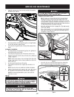
Locate the flange lock nut (a) on the front end of the PTO lift rod (b). See Figure 17.
(a)
(b)
Figure 17
a. Tighten the fla nge lock nut (a) to raise the front of the deck.
b. Loosen the flange lock nut (a) to lower the front of the deck.
Tires
Refer to the Assembly & Set-Up section for more information regarding tire pressure.
Service
Cutting Deck Removal
To remove the cutting deck, proceed as follows:
1.
Remove power key and engage the parking brake.
2.
Lower the deck by moving the deck lift lever into the lowest (#1) position on
the right fender.
3.
Remove the bow-tie cotter pin (a) and flat washer (b) from the deck lift
assembly, and retain for reinstallation later. See Figure 18.
(a)
(b)
Figure 18
4.
Disconnect the deck motor(s) from the adapters on the underside of the
tractor. Rotate the collar on the larger connector (a) counterclockwise and
carefully pull apart. Repeat the procedure with the smaller connector (b).
Note:
Your mower may have one of two different deck motor connector
setups. If your mower has horizontally positioned connectors, see Figure 19.
If your mower has vertically positioned connectors, see Figure 20.
(a)
(b)
Figure 19
(a)
(b)
Figure 20
Note:
Always disconnect the larger connector first.
5.
Remove the remaining bow-tie cotter pins (a)
securing the deck to the tractor, as shown in Figure 21.
(a)
(a)
Figure 21
Summary of Contents for CMXGRAM1130049
Page 46: ...NOTES 46 ...
Page 47: ...NOTES 47 ...


