


19
MAINTENANCE
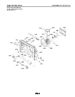
1. With the auger control lever released, the hook (
A
, Figure 14)
should barely touch the lever (
B
) without raising it. There can
be a maximum of 1/32 in. (0.8 mm) clearance.
2. To adjust, loosen the nut (
C
) by holding the adjusting flats (
D
)
and turning the nut. Then, turn the adjusting flats and hold the
adjustment screw (
E
). The adjustment screw is a phillips screw
and the head can be held or turned by inserting a screwdriver
through the spring (
F
).
3. Hold the adjusting flats and tighten the nut.
4. Start the engine and check the auger. The auger must not be
engaged unless the auger control lever is depressed.
5. With the engine running, fully depress the auger drive control
lever. The auger should engage and run normally.
1/32"
(0.8mm)
A
B
C
D
E
F
WARNING: Do not over-tighten, as this may lift the
lever and cause the auger drive to be engaged
without depressing the auger drive control.
Figure 14
AUGER CONTROL CABLE ADJUSTMENT
WARNING: The auger must stop within 5 seconds. If it
does not, see an authorized dealer.
8. If the drive linkage is properly adjusted, the tension of the
auger drive belt may require an adjustment. See an authorized
dealer.
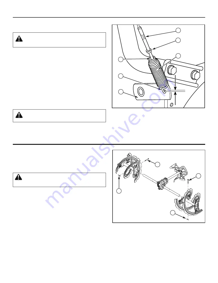
AUGER SHEAR PIN REPLACEMENT
The augers are secured to the auger shaft with special shear pins
that are designed to break if an object becomes lodged in the
auger housing. Use of a harder grade shear pin will reduce the
protection provided by the shear pin.
WARNING: Do not go near the discharge chute or
auger when the engine is running. Do not run the
engine if any cover or guard is removed.
Under most circumstances, if the auger strikes an object which
could cause damage to the unit, the shear pin will break. This pro-
tects the gear box and other parts from damage. The shear pins
(
A
, Figure 15) are located on the auger shaft. Replace a broken
shear pin as follows.
1. Stop the engine, disengage all controls, disconnect the spark
plug lead wire, and make sure all moving parts have stopped.
2. Tap out the broken shear pin with a pin punch.
3. Align the hole in the auger with the hole in the auger shaft. In-
stall a new shear pin (
A
, Figure 15) and cotter pin (
B
). Bend
the ends of the cotter pin down.
IMPORTANT: Do not replace shear pins with anything
other than the correct grade replacement shear pin. Use
of bolts, screws, or harder grade shear pins can result in
equipment damage.
Figure 15
B
B
A
A
6. Release the auger control lever.
7. If the auger does not operate properly, stop the engine and
recheck the auger control cable adjustment.
Summary of Contents for C950-52122-0
Page 2: ...2 ...
Page 25: ...25 ...
Page 27: ...Repair Parts PTS 1 ...
Page 58: ...PTS 32 ...
Page 60: ...2 ...
Page 85: ...27 ...
Page 87: ...29 ...
Page 88: ......