background image

1

OPERATION

gas & Oil Fill-Up 

Service the engine with gasoline and oil as instructed in the separate 
engine manual packed separately with your snow thrower. Read 
instructions carefully.

WARNING: Use extreme care when handling 
gasoline. Gasoline is extremely flammable and 
the vapors are explosive. 

Never

 fuel the machine 

indoors or while the engine is hot or running. 
Extinguish cigarettes, cigars, pipes and other 
sources of ignition.

Starting The Engine

WARNING: Be sure no one other than the operator 
is standing near the snow thrower while starting 

engine or operating snow thrower. Never run engine 
indoors or in enclosed, poorly ventilated areas. 
Engine exhaust contains carbon monoxide, an 
odorless and deadly gas. Keep hands, feet, hair 
and loose clothing away from any moving parts on 
engine and snow thrower. 

1.  Attach spark plug wire to spark plug. Make certain the metal 

loop on the end of the spark plug wire (inside the rubber boot) is 
fastened securely over the metal tip on the spark plug. 

2.  Make certain both the auger control and drive control are in the 

disengaged (released) position.

3.  Move throttle control up to FAST position. Insert ignition key into 

slot. Make sure it snaps into place. Do not attempt to turn the key.

NOTE:

 The engine cannot start unless the key is inserted into ignition 

switch. 

Electric Starter

1.  Determine that your home’s wiring is a three-wire grounded system. 

Ask a licensed electrician if you are not certain.

WARNING: The optional electric starter is equipped 
with a grounded three-wire power cord and 
plug, and is designed to operate on 120 volt AC 
household current. It must be used with a properly 
grounded three-prong receptacle at all times to 
avoid the possibility of electric shock. Follow all 
instructions carefully prior to operating the electric 
starter. 

If your home’s wiring system is not a three-wire grounded 
system,

 do not use this electric starter under any conditions.

If your home electrical system is grounded, but a three-hole 
receptacle is not available,

 one should be installed by a licensed 

electrician before using the electric starter.

If you have a grounded three-prong receptacle,

 proceed as follows:

1.  Plug the extension cord into the outlet located on the engine’s 

surface. Plug the other end of extension cord into a three-prong 
120-volt, grounded, AC outlet in a well-ventilated area. 

2.  Rotate choke control to FULL choke position (for a cold engine 

start). 

NOTE:

 If the engine is already warm, place choke control in the OFF 

position instead of FULL.
3.  Push the primer two or three times for cold engine start, making 

sure to cover vent hole in the center of the primer when pushing. 

NOTE:

 DO NOT use primer to restart a warm engine after a short 

shutdown.
4.  Push starter button to start engine.
5.  Once the engine starts, immediately release starter button.
6.  As the engine warms, slowly rotate the choke control to the OFF 

position. If the engine falters, quickly rotate the choke control back 
to FULL and then slowly into the OFF position again.

7.  When disconnecting the extension cord, always unplug the end at 

the three-prong wall outlet before unplugging the opposite end from 
the snow thrower.

Recoil Starter

1.  Rotate choke control to FULL choke position (cold engine start). 

NOTE:

 If the engine is already warm, place choke control in the OFF 

position instead of FULL.
2.  Push the primer two or three times for cold engine start, making 

sure to cover vent hole in the center of the primer when pushing. 

NOTE:

 DO NOT use primer to restart a warm engine after a short 

shutdown.

NOTE:

 Additional priming may be necessary if the temperature is 

below 15° F. (-9° C).
3.  Grasp the recoil starter handle and slowly pull the rope out. At the 

point where it becomes slightly harder to pull the rope, slowly allow 
the rope to recoil.

4.  Pull the starter handle with a firm, rapid stroke. Do not release the 

handle and allow it to snap back. Keep a firm hold on the starter 
handle and allow it to slowly recoil.

5.  As the engine warms, slowly rotate the choke control to the OFF 

position. If the engine falters, quickly rotate the choke control back 
to the FULL position and then slowly into the OFF position again.

NOTE:

 Allow the engine to warm up for a few minutes after starting. 

The engine will not develop full power until it reaches operating 
temperatures.

Summary of Contents for C459-527870

Page 1: ... follow all safety rules and operating instructions Operator s Manual SAFETY ASSEMBLY OPERATION MAINTENANCE PARTS LIST SEARS CANADA 222 Jarvis St Toronto On M5B 2B8 Visit our website sears ca 8 22 2007 FORM NO 769 03337 45 SNOW THROWER Model No C459 527870 ...

Page 2: ... 199260 07 21 05 BY Printed in U S A 02488 ...

Page 3: ...h become worn during normal use such as belts spark plugs air cleaners and shear pins as well damage to the engine resulting from operating snow thrower with insufficient oil Repairs necessary because of operator abuse or negligence including the failure to operate and maintain the equipment according to the instructions contained in the Owner s Manual Tire replacement or repair caused by puncture...

Page 4: ...gine is running except where specifically recommended in the operator s manual 8 Let engine and machine adjust to outdoor temperature before starting to clear snow Safe Handling of Gasoline To avoid personal injury or property damage use extreme care in handling gasoline Gasoline is extremely flammable and the vapors are explosive Serious personal injury can occur when gasoline is spilled on yours...

Page 5: ...es until all moving parts have stopped before unclogging 19 Use only attachments and accessories approved by the manufacturer e g wheel weights tire chains cabs etc 20 If situations occur which are not covered in this manual use care and good judgment Contact your Sears Service Center for assistance Maintenance Storage 1 Never tamper with safety devices Check their proper operation regularly Refer...

Page 6: ...mbly of ice and snow This item is fastened with a cable tie at the factory Cut the cable tie before operating the snow thrower WARNING Never use your hands to clear a clogged chute assembly Shut off engine and remain behind handles until all moving parts have stopped before using the clean out tool to clear the chute assembly Chute Clean out Tool ...

Page 7: ...ide of machine are observed from the operating position Assembling Handle Look at the lower rear of the snow thrower frame to be sure the spring found at the end of each cable is attached to its actuator bracket Remove the lower handle knobs washers and carriage bolts from each side of the lower handle See Figure 2 Raise the upper handle assembly until it locks over the lower handle See Figure 1 S...

Page 8: ...rod Tap the connector until the lower rod is completely through the connector See Figure 6 NOTE If the connector is not properly assembled the shift rod will pivot and you will not be able to change speeds or direction NOTE If the full range of speeds forward and reverse cannot be achieved refer to the Adjustment Section Normally the cable ties holding the steering cables against the handle are lo...

Page 9: ...perating on gravel or crushed rock surfaces See Making Adjustment Section Tire Pressure Pneumatic Tires The tires are over inflated for shipping purposes Check the tire pressure before operating the snow thrower Refer to the tire side wall for tire manufacturer s recommended psi and deflate or inflate the tires as necessary IMPORTANT If the tire pressure is not equal in both tires the unit may not...

Page 10: ...ure the throttle is set in the fast position While standing in the operator s position behind the snow thrower engage the auger Allow the auger to remain engaged for approximately ten seconds before releasing the auger control Repeat this several times With the engine running in the fast position and the auger control lever in the disengaged up position walk to the front of the machine Confirm tha...

Page 11: ...now thrower for operation get acquainted with its controls and features These are described below and illustrated on this page This knowledge will allow you to use your new equipment to its fullest potential NOTE For detailed starting instructions and more information on all engine controls refer to the separate engine manual packed with your unit Shift Lever The shift lever is located in the cent...

Page 12: ...are located on the underside of the handles Squeeze the right control to turn right squeeze the left control to turn left NOTE Operate the snow thrower in open areas until you are familiar with these controls Ignition Key The ignition key must be inserted and snapped in place in order for the engine to start Remove the ignition key to prevent unauthorized use of equipment Do NOT attempt to turn th...

Page 13: ...sed electrician before using the electric starter If you have a grounded three prong receptacle proceed as follows 1 Plug the extension cord into the outlet located on the engine s surface Plug the other end of extension cord into a three prong 120 volt grounded AC outlet in a well ventilated area 2 Rotate choke control to FULL choke position for a cold engine start NOTE If the engine is already w...

Page 14: ...he auger control the interlock mechanism should keep the auger control engaged until the drive control is released 4 Release the drive control to stop both the augers and the wheel drive To stop the auger both levers must be released Operating Tips NOTE Allow the engine to warm up for a few minutes The engine will not develop full power until it reaches operating temperature WARNING The temperatur...

Page 15: ... the ferrule into the proper hole 6 Reinstall the washer and the internal cotter pin Drive Control Refer to the Final Adjustment section of the Set Up instructions to adjust the drive control To further check the adjustment proceed as follows 1 Drain the gasoline out of your snow thrower s engine and place a piece of plastic film under the gas cap to avoid spillage 2 Tip the snow thrower forward a...

Page 16: ... not remove the hex flange locknuts which fasten the skid shoe to the auger housing 2 Raise or lower the skid shoe to desired position 3 Retighten the hex nuts loosened earlier NOTE Make certain the bottom surface of skid shoe is flat against the ground to avoid uneven wear 4 Repeat on the other side of the snow thrower Auger Control Refer to instructions on page 9 to adjust the auger control Make...

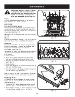
Page 17: ...t See Figure 20 Shave Plate and Skid Shoes The shave plate and skid shoes on the bottom of the snow thrower are subject to wear They should be checked periodically and replaced when necessary To remove skid shoes 1 Remove the carriage bolts and washers if equipped and hex flange nuts which secure the skid shoes to the snow thrower 2 Reassemble new skid shoes with previously removed hardware Refer ...

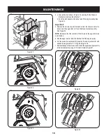
Page 18: ...m the brake bracket assembly See Figure 25 NOTE Make sure that the location of the ferrule on the auger idler rod is maintained 5 Slip the auger control belt the front belt off the engine pulley 6 Pull the brake bracket assembly towards the cable guide roller and unhook the auger cable Z fitting See Figure 26 7 Remove the upper hex screws which attach the auger housing assembly to the frame assemb...

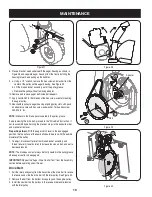
Page 19: ...cing the drive belt proceed to the Drive Belt instruction If not reassemble by performing the previous steps in the opposite order and manner of removal Proper Adjustment With the auger clutch lever in the disengaged position the top surface of the new belt should be even with the outside diameter of the pulley 1 To adjust disconnect ferrule from brake bracket assembly and thread ferrule in toward...

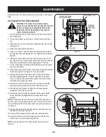
Page 20: ...le shaft and the drive shaft assemblies 8 Remove four screws securing the friction wheel rubber between the friction wheel plates See Figure 32 Discard old rubber 9 Reassemble the new friction wheel rubber to the friction wheel assembly tightening the four screws in rotation and with equal force It is important to assemble the rubber on the friction wheel symmetrically for proper functioning 10 In...

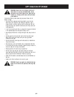
Page 21: ...ntil fuel tank is empty and engine stops due to lack of fuel Remove gasoline from carburetor and fuel tank to prevent gum deposits from forming on these parts and causing possible malfunction of engine Drain carburetor by pressing upward on bowl drain located below the carburetor cover Fuel stabilizers such as STA BIL are an acceptable alternative in minimizing the formation of fuel gum deposits d...

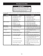
Page 22: ...re Remove ice and snow from gas cap Be certain vent hole is clear 1 2 Unit fails to propel itself Drive cable in need of adjustment Drive belt loose or damaged 1 2 Adjust drive control cable Refer to Maintenance section Replace drive belt Refer to Maintenance section 1 2 Unit fails to discharge snow Chute assembly clogged Foreign object lodged in auger Auger cable in need of adjustment Auger belt ...

Page 23: ...NOTES 23 ...

Page 24: ...42 25 70 71 52 57 56 49 63 44 43 52 58 21 5 26 33 38 20 19 34 3 19 32 21 2 39 7 36 14 1 41 19 19 35 29 31 19 68 47 60 61 2 64 65 71 4 59 51 28 45 57 40 48 31 62 69 66 67 24 47 37 27 15 16 10 18 47 68 53 54 69 16 55 46 9 8 23 28 11 28 12 13 30 22 ...

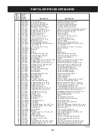
Page 25: ...3A Lower Shift Rod Tige de commande inférieur 36 747 0997 Upper Shift Rod Tige de commande supérieur 37 784 5680 RH Handle Support Brkt 5 8 Support de guidon droit 5 8 po 38 749 0989A Upper Handle LH Guidon supérieur CG 39 749 0990A Upper Handle RH Guidon supérieur CD 40 749 0991 Lower Handle Guidon supérieur 41 750 0963 Connector Shift Rod Raccord tige de changement de la vitesse 42 684 0102A Han...

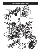
Page 26: ...67 23 2 42 54 38 4 43 43 24 71 24 86 80 18 66 3 63 40 38 69 48 31 10 63 6 93 88 64 17 62 7 37 39 33 65 78 16 57 30 45 55 47 76 61 75 14 79 91 85 22 78 89 46 84 44 81 49 90 34 34 5 68 17 Torque to 325 550 in lbs Serrez à un couple de 325 550 po lb Torque to 325 550 in lbs Serrez à un couple de 325 550 po lb 26 B Tec 94 95 29 Tec OHV 358 cc Tec LH 358 cc OHV 318 cc Tec Tec 79 ...

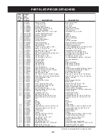
Page 27: ... x 0 75 32 712 0717 Nut Insert 3 8 16 UNC Écrou inserer 3 8 16 UNC 33 713 0284 41 Chain 1 2 pitch x 36 links Endless Chaîne no 41 pas de 1 2 po x 36 maillons 34 713 0286 420 Chain 1 2 pitch x 40 links Endless Chaîne no 420 pas de 1 2 po x 40 maillons 35 713 04015 10T Sprocket 41 x 500 Pignon 10 dents 36 714 0135 Woodruff Key Clavette 37 714 0104 Int Cotter Pin 5 16 DIA Goupille fendue 5 16 DIA 38 ...

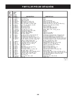
Page 28: ...16 18 x 50 Vis auto taraudeuse hexagonal 5 16 18 x 0 50 81 710 1245B Hex HD Cap Scr 5 16 24 x 0 875 Lg Gr 8 Vis à tête hexagonal 5 16 24 x 0 875 po de lg Qual 8 710 0672 Hex HD Cap Scr 5 16 24 x 1 25 Lg Gr 5 Vis à tête hexagonal 5 16 24 x 1 25 po de lg Qual 5 358 cc L Head 318 cc OHV 358 cc L Head 318 cc OHV 82 710 0654A Hex Wash HD Tap Scr 3 8 16 x 1 00 Vis autotaraudée 3 8 16 x 1 00 83 736 0173 ...

Page 29: ...063 Hex Flange Locknut 5 16 18 Gr F Nylon Contre écrou à embase 5 16 fil 18 Qual F 4 710 1003 Hex Tapp Wash Hd Scr 10 x 5 8 Vis n 10 x 5 8 5 625 0007A Top Mounting Halogen Lamp Assembly Phare à iode 6 710 1240 Phillips Pan Hd Scr M4 x 16mm Vis Phillips à tête cylindrique M4 x 16mm 7 731 1364 Halogen Lamp Housing Boîtier du phare à iode 8 725 1669 Lamp Lens Housing Ass y Boîtier du phare optique 9 ...

Page 30: ...ve asphalt Set to maximum for gravel driveways La plaque de râclage doit être légèrement au dessus du goudron Réglez la au maximum en cas d allées gravillonnées When rebuilding gear box fill one housing half completely with grease 838 0168 Pour remonter la boîte d engrenages remplissez complètement une moitié avec de la graisse no 838 0168 Torque to 20 30 in lbs Serrez à un couple de 20 30 po lb 4...

Page 31: ...4 04224 Snowthrower Housing Ass y Logement du chasse neige 46 790 00280 Shave Plate Plaque de raclage 47 749 1117 Support Tubing Tuyau 48 737 0318 Arctic Grease Graisse Arctic 49 684 04151 Augers RH Tarières CD 684 04152 Augers LH Tarières CG 50 784 5697 Reversible Slide Shoe Sabot coulissant réversible 51 618 04515 Worm Gear Box Ass y Boîte d assemblage de vis sans fin 52 710 3168 Carriage Bolt 3...

Page 32: ...3 PARTS LIST Craftsman Engine Model OH358SA 223828 For Snow Thrower Model C450 527870 ...

Page 33: ...tension 65 30200 Screw 10 24 x 9 16 69 35683 Cylinder Cover Gasket Ref No Part No Description 70 35684A Cylinder Cover Incl 14 15 20 38 71 35377 Crankshaft Bushing 80 35751 Governor Shaft 81 35479A Washer 82 35321 Governor Gear Assembly 83 35322 Governor Spool 84 29193 Retaining Ring 86 650833 Screw 1 4 20 x 1 3 16 87 650832 Screw 1 4 20 x 1 11 16 89 32589 Flywheel Key 90 611093 Flywheel 3 Amp w r...

Page 34: ...Screw 10 32 x 1 2 260 37092A Blower Housing Ref No Part No Description 262 651084 Screw 5 16 18 x 9 16 265 37086 Cylinder Head Cover 266 650876 Screw 5 16 18 x 1 9 32 269 35762 Exhaust Manifold Gasket 270 37263 Exhaust Manifold 270A 35829A Exhaust Port Liner 271 35293 Locking Plate Manifold 275 37264 Muffler 276 35348 Locking Plate 277A 650877 Screw 5 16 18 x 4 1 2 280 37265 Heat Shield 285 35985C...

Page 35: ...nal Symbol 370 37226 Decal Speed Control Choke Key 380 640105 Carburetor Incl 184 390 590749 Rewind Starter 396 37105 Electric Starter Motor 120 Volt Optional 400 36947B Gasket Set Incl items marked Incl items marked 420 730226A SAE 5W30 4 Cycle Engine Oil Quart Winter 704 650738 Screw 1 4 20 x 5 8 710 36482 Compression Spring 711 651019 Screw T 10 6 32 x 41 64 730286 Winter Maintenance Kit includ...

Page 36: ...NOTES 23 ...

Page 37: ...NOTES 23 ...

Page 38: ...NOTES 23 ...

Page 39: ...achées et de répara tions Sears Vibration excessives 1 Pièces desserrées ou vis sans fin endommagée 1 Arrêtez le moteur immédiatement et débranchez le fil de la bougie Serrez tous les boulons et écrous Si la vibration continue faites entretenir l unité par un centre de pièces et réparation Sears Perte de puissance 1 Fil de la bougie desserré 2 Le port déchappement est bouché 1 Branchez et serrez l...

Page 40: ...e qu il s arrête pour cause de panne d essence Videz toute l essence du carburateur et du réservoir pour éviter la formation de dépôts de gomme qui pourraient causer le mauvais fonctionnement du moteur Videz le carburateur en appuyant sur l évacuation qui se trouve sous le couvercle du carburateur Les agents de stabilisation du carburant STA BIL par exemple offrent une solution acceptable pour min...

Page 41: ...ignon devrait rester accroché dans la chaîne 7 Dégagez la roue de frottement entre l arbre de l essieu et l arbre d entraînement 8 Enlevez les quatre vis de l ensemble de la roue de frottement et retirez le caoutchouc de la roue de frottement de la plaque de serrage Voir la Figure 32 Jetez le vieux caoutchouc 9 Installez le nouveau caoutchouc de la roue de frottement sur la roue de frottement Serr...

Page 42: ...ez en utilisant la vis hex et la rondelle Serrez la vis à un couple de 250 à 325 po lb REMARQUE Vérifiez que le galet du frein est bien enfoncé dans la gorge de la poulie Si vous remplacez aussi la courroie d entraînement suivez les instructions du paragraphe Courroie d entraînement Sinon procédez dans le sens inverse au démontage Réglage correct Quand la commande de la tarière n est pas enclenché...

Page 43: ...roie et le support de la poulie motrice Voir la Figure 24 Courroie d entraînement de la tarière 4 Retirez la goupille fendue et la rondelle plate de la virole pour dégager la tige de tension de la tarière du support du frein comme à la Figure 25 REMARQUE Assurez vous de ne pas déplacer la virole sur la tige de tension de la tarière 5 Dégagez la courroie d entraînement de la tarière courroie avant ...

Page 44: ...ison Vaporisez un lubrifiant à l intérieur de l arbre et autour des entretoises Lubrifiez aussi les roulements à bride trouvés à chaque extrémité de l arbre de la tarière Voir la Figure 20 Lame et patins La lame plate et les patins sont installés sous la souffleuse et ils ris quent de s user Vérifiez les régulièrement et remplacez les au besoin Pour démonter les patins 1 Enlevez les boulons ordina...

Page 45: ...la position voulue 3 Serrez les écrous à six pans desserrés plus tôt REMARQUE Vérifiez que toute la surface inférieure des patins est de niveau et en contact avec le sol pour éviter leur usure inégale 4 Répétez l ajustement sur l autre patin Commande de la tarière Consultez les instructions à la page 9 pour ajuster la commande de la tarière Vérifiez bien que l ajustement est correct avant d utilis...

Page 46: ... interne Commande de l entraînement des roues Consultez la partie concernant le Réglage final dans le chapitre Instructions de Montage pour régler la commande d entraînement Pour vérifier ce réglage procédez comme suit 1 Videz l essence qui se trouve dans le moteur de la souffleuse et placez un morceau de plastique sous le bouchon d essence pour éviter tout renversement 2 Basculez la souffleuse ve...

Page 47: ...permet de bloquer la commande de la tarière pour permettre au conducteur puisse orienter la goulotte sans cesser de projeter la neige 3 Débrayez la commande de la tarière le mécanisme de blocage maintient la tarière engagée jusqu à ce que la commande de la transmission soit débrayée 4 Lâchez la commande de la transmission pour arrêter la tarière et les roues Pour arrêter la tarière les deux poigné...

Page 48: ...eur Suivez soigneuse ment toutes les instructions avant d utiliser le démarreur électrique Si le câblage de votre maison n est pas un système à trois fils reliés à la terre n utilisez en aucun cas ce démarreur électrique Si votre système est relié à la terre mais s il n y a pas de prise à trois trous à l endroit où le démarreur doit normalement être utilisé n utilisez en aucun cas ce démarreur éle...

Page 49: ...sens inverse pour décharger la neige à droite Commande d orientation des roues Les commandes d orientation des roues de droite et de gauche se trouvent en dessous des poignées Serrez la commande de droite pour tourner vers la droite ou serrez celle de gauche pour tourner vers la gauche REMARQUE Utilisez la souffleuse dans des espaces dégagés jusqu à ce que vous soyez plus habitué aux commandes Clé...

Page 50: ...expliquées ci dessous et représentées sur ce page Vous pourrez ainsi bénéficier au maximum de votre nouvelle machine REMARQUE Consultez la notice d utilisation du moteur emballée séparément avec votre souffleuse pour avoir plus de renseignements concernant le démarrage et les commandes du moteur Levier de vitesses Il se trouve au milieu du tableau de bord et sert à choisir la vitesse et la directi...

Page 51: ... aéré et faites démarrer la souffleuse selon les instructions de la page 12 Vérifiez que l obturateur est réglé à la position rapide Tenez vous à la position de conduite derrière la souffleuse et enclenchez la tarière Attendez environ dix secondes avant de débrayer la tarière Répétez cette opération plusieurs fois Laissez tourner le moteur à plein régime et gardez la commande de la tarière à la po...

Page 52: ...z les si la neige est tassée et abaissez les pour travailler sur des surfaces recouvertes de gravier ou de pierre concassée Consultez le chapitre Réglages Pression des pneus Bandages pneumatiques Les pneus sont gonflés excessivement pour l expédition Avant l utilisation vérifiez la pression des pneus avant d utiliser la souffleuse La pression recommandée par le fabricant est indiquée sur le flanc ...

Page 53: ... abaissez le raccord des tiges sur l extrémité de la tige du levier de vitesses inférieure Tapez sur le raccord jusqu à ce qu il passe bien à travers la tige du levier de vitesses inférieure Voir la Figure 6 REMARQUE Si le raccord n est pas bien installé la tige du levier de vitesses pivotera et il sera impossible de changer de vitesse ou de direction REMARQUE S il n est pas possible d utiliser to...

Page 54: ...derrière la souffleuse Montage du guidon Vérifiez que tous les câbles sont alignés avec les galets de guidage sur l arrière du châssis de la souffleuse avant de redresser le guidon Assurez vous que le ressort qui se trouve à l extrémité de chaque câble est attaché à son support Enlevez les boutons et les boulons ordinaires inférieurs de chaque côté du guidon inférieur Voir la Figure 2 Relevez le g...

Page 55: ... Cet outil a été fixé avec un attache câble à l usine Coupez l attache câble avant de mettre la souffleuse en marche AVERTISSEMENT Ne vous servez jamais de vos mains pour dégager une obstruction dans la goulotte Arrêtez le moteur et restez derrière les guidons jusqu à ce que toutes les pièces se soient arrêtées avant de vous servir de l outil de dégagement pour nettoyer la goulotte Outil de dégage...

Page 56: ...moteur tourne Arrêtez le guidon jusqu à ce que toutes les pièces en mouvement se soient immobilisées avant de déboucher la goulotte 19 N utilisez que des accessoires homologués par le fabricant de la machine ex poids de roues chaînes cabine etc 20 Faites toujours preuve de bon sens dans des situations qui n ont pas été abordées par cette notice d utilisation Contactez votre Centre de Service Sears...

Page 57: ...ur pendant qu il tourne à moins d indications contraires de la part du fabricant 8 Laissez le moteur et la machine s habituer à la température extérieure avant de commencer à déblayer Manipulation de l essence Pour éliminer tout risque de blessure grave faites très attention en manipulant de l essence Il s agit d un produit extrêmement inflammable et les vapeurs risquent d exploser Vous pouvez êtr...

Page 58: ...ant la livraison Les pièces courantes à usure normale comme les courroies les bougies les filtres à air et les goupilles de cisaillement ainsi que tout dégât au moteur résultant de l utilisation de la souffleuse avec une quantité d huile insuffisante Les réparations nécessaires en raison de l utilisation abusive ou négligente y compris l utilisation et l entretien de l équipement ne re spectant pa...

Page 59: ... proche afin d apporter à l atelier des produits tels que des aspirateurs tondeuses à gazon ou appareils électroniques Pour connaître le no de téléphone du Service des pièces et de l entretien Sears afin de commander les pièces de rechange accessoires et manuels d instructions requis pour effectuer vous même les réparations www sears ca Pour acheter ou demander des renseignements sur un contrat d ...

Page 60: ... web sears ca ATTENTION Lisez attentivement les régles de sécurité et les instructions avant de mettre en marche la machine Notice d utilisation SÉCURITÉ MONTAGE UTILISATION ENTRETIEN PIÈCES DÉTACHÉES 8 22 2007 FORM NO 769 03337 45 SNOW THROWER Model No C459 527870 ...

Reviews: