


21
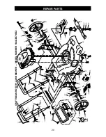
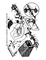
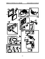
CRAFTSMAN ROT
AR
Y
LA
WN MOWER - - MODEL
NUMBER
944.367652
NOTE:
All component dimensions given in U.S. inches. 1 inch = 25.4 mm.
IMPORT
ANT
: Use only Original Equipment Manufacturer (O.E.M.) replacement parts. Failure to do so could be hazardous, damage your lawn mo
wer and void your warranty
.
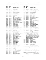
26
409149
Hex Flange Nut
27
407773X460
Wheel & Tire
Assembly
28
401638
Shoulder Bolt 5/16-18 x .33
29
41
1
1
90
T
rimplate
30
401
181X004
Axle
Arm
Assembly
, Rear
, RH
31
701037
Selector Knob
32
401626X004
Selector Spring
33
73800500
Nut, Hex 5/16-18
34
401630
W
a
sher
, Curved, Cylindrical
35
141841
Screw
36
184193
Bolt
37
74780512
Screw 5/16-18 x 3/4
38
401629
Spacer
39
198541
Nut, Hex 3/8-16
40
188839X004
Mounting Bracket,
Debris Shield
41
192325
Screw
, Debris Shield
42
175551
Screw
43
405844
Debris Shield
44
4131
15
Kit, Mower Housing (Includes
Key Numbers 10, 1
1, 12, 45)
45
404763
Danger Decal
46
194037
Blade
Adapter / Pulley
47
406706
Blade, 21"
48
851074
Hardened W
asher
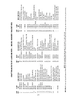
KEY
P
ART
NO.
NO.
DESCRIPTION
1
194200X479
Upper Handle
2
175245X479
Lower Handle
3
194199X428
Control Bar
4
1741
1308
Screw
5
191574
Handle Bolt
6
189713X428
Handle Knob
7
51793
Hairpin Cotter
8
66426
W
ire Tie
9
401812X428
Rear Door
Assembly
10
128415
Pop Rivet
1
1
406573
Support Bracket, LH
12
406574
Support Bracket, RH
13
17060410
Screw 1/4-20 x 5/8
14
175576X479
Handle Bracket
Assembly
, LH
15
175577X479
Handle Bracket
Assembly
, RH
16
405417
Spring, Rear Door
, LH
17
405418
Spring, Rear Door
, RH
18
132004
Keps Locknut 1/4-20
19
194788
Rope Guide
20
189005
Rear Skirt
21
88652
Hinge Screw 1/4-20 x 1-1/4
24
- - -
Engine, Briggs & Stratton,
Model Number 126T05-
0880-B2 (See Breakdown)
25
150406
Screw
, Hex Head, Threaded,
Rolled 3/8-16 x 1-1/8
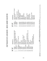
KEY
P
ART
NO.
NO.
DESCRIPTION
49
850263
Helical W
asher
50
851084
Screw
, Machine, Hex Head,
Grade 8 3/8-24 x 1-3/8
51
189686
Key Start Switch
(Includes Key)
52
189589
Battery
53
186159
Screw
54
186237
Battery Box
55
180331
Key
56
191252
T
rimplate/Battery
Assembly
57
850733X004
Upstop Bracket
58
750634
Screw
59
175071
Discharge Defl
ector
60
175735
Hinge Bracket
61
193000
Spring, T
orsion
62
175650
Hinge Rod
63
73800400
Nut, Hex
64
175066
Mulcher Door
65
197480
O-Ring
66
88348
W
a
sher
, Flat
67
190097
Charger
96
197991
Clip, Cable
- -
404764
W
a
rning Decal (not shown)
- -
413755
Owner’s Manual, English
- -
413756
Owner’s Manual, French
KEY
P
ART
NO.
NO.
DESCRIPTION