background image

FOR YOUR 
SAFETY:

READ ALL 
INSTRUCTIONS 
CAREFULLY

Save This Manual

For Future Reference

owner’s

manual

Part No. SP5984

Printed in U.S.A.

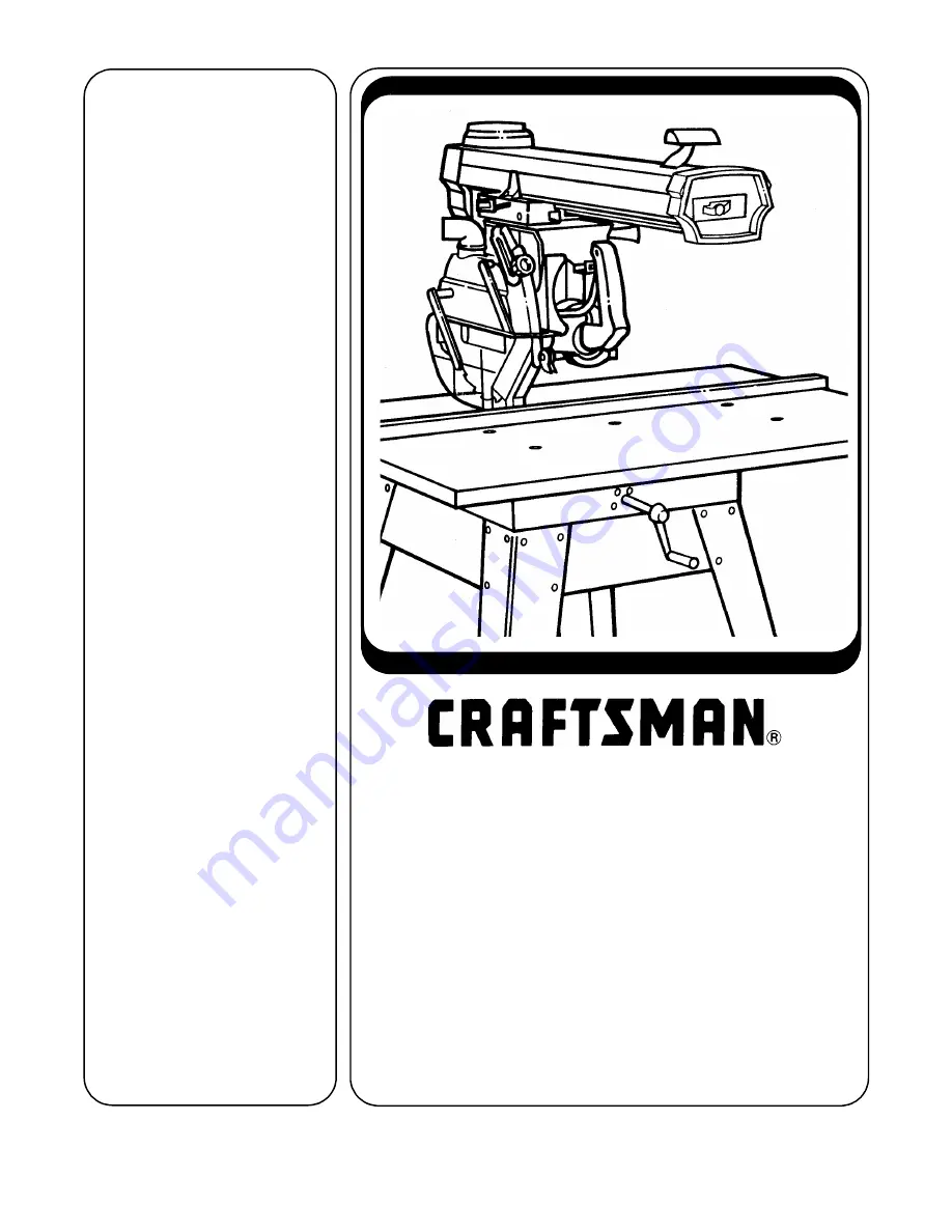
10-INCH RADIAL SAW

GUARD KIT

• assembly
• operating
• repair parts

MODEL NO.

509347

509347 FITS THE 

FOLLOWING RADIAL 

SAWS:

113.19930, 113.197731,
113.197732, 113.199350

Summary of Contents for 509347

Page 1: ...LLY Save This Manual For Future Reference owner s manual Part No SP5984 Printed in U S A 10 INCH RADIAL SAW GUARD KIT assembly operating repair parts MODEL NO 509347 509347 FITS THE FOLLOWING RADIAL SAWS 113 19930 113 197731 113 197732 113 199350 ...

Page 2: ...ual If you no longer have your saw s owners manual call customer service at 1 800 325 1184 Have your saw s model num ber when you call 2 If you require this manual in Spanish or French call 1 800 511 2628 Si usted requiere que éste manual usuario en español o francés llame 1 800 511 2628 Pedir for mulario SP5984S 2 Si vous nécesstent ce mode d emploi en espagnol ou français téléphonez au 1 800 511...

Page 3: ...ty informa tion is not followed someone will be seri ously injured or killed WARNING means if the safety informa tion is not followed someone could be seri ously injured or killed CAUTION means if the safety informa tion is not followed someone may be injured Read and follow all safety information and instructions Major Hazards Three major hazards are associated with using the radial arm saw for r...

Page 4: ...death Read and follow the information and instructions under ripping safety Wrong Way Feed Hazard Wrong way feed is ripping by feeding the workpiece into the outfeed side of the blade The rotational force of the blade can grab and pull the workpiece Before you can let go or pull back the force could pull your hand along with the work piece into the blade Fingers or hand could be cut off The propel...

Page 5: ...th the outfeed side of the blade during ripping and acts as a barrier to prevent wrong way feed 3 A squeeze trigger in the saw handle to fully raise the clear plastic guard at the start of a crosscut Note This is necessary because the guard will not automatically raise to clear the fence 4 A hold down to be lowered to just clear the top of the workpiece for ripping It acts as a barrier to the infe...

Page 6: ...ny protection during cross cutting if blade is pulled over your hand or your hand enters blade path from front or rear of blade Fingers or hand can be cut or cut off CAUTION Clear plastic portion of guard can get caught or jam in fence or table kerfs Read and follow the warning on the guard WARNING TO AVOID INJURY SHUT OFF POWER BEFORE CLEARING A JAMMED LOWER GUARD WARNING Clear plastic guard will...

Page 7: ...p from inhaling fine particles 4 Wear ear protectors plugs or muffs if you use saw daily 5 Keep good footing and balance do not over reach Work Area Safety Instructions 1 Keep children pets and visitors out of work area they could be hit by a thrown workpiece workpiece chips or pieces of blade 2 Turn saw off remove yellow key and unplug before leaving work area Do not leave until blade has stopped...

Page 8: ...lear table of all objects except workpiece to be cut and nec essary fixtures clamps or feather boards 7 If blade jams turn saw off immediately remove yellow key then free blade Do not try to free blade with saw on 8 Turn saw off if it vibrates too much or makes an odd sound Correct any problem before restarting saw 9 Do not layout assemble or setup work with saw on or while blade is spinning 10 Ke...

Page 9: ...ter Safety 3 Rip only workpieces longer than the diameter of the blade Do not rip workpieces that are shorter than the diameter of the blade being used 4 Workpieces that extend beyond the saw table can shift twist rise up from the table or fall as they are cut or afterwards Support workpiece with table extensions the same height as the saw table 5 To prevent tipping support outer ends of extension...

Page 10: ...ng way feed On the infeed side of the guard is this safety label to remind you to lower the hold down to just clear the top of the workpiece for ripping On the rear of the yoke visible from the infeed side when the saw is in a rip position is this safety label to alert you to outfeed zone hazard Note where they are located on the saw Read and follow the safety information and instructions in these...

Page 11: ...astic guard is this OSHA required label On the bottom surface of the motor visible when the cutting tool is horizontal is this safety label alerting you to use a guard when edge molding and to position the cutting tool behind the fence see Accessories Section On the front of the yoke is this general safety instruction label Safety ...

Page 12: ...ck packaging for missing parts before contacting Emerson Tool Co A complete parts list Repair Parts is at the end of the manual Use the list to iden tify the number of the missing part Assembly List of loose parts with model 509347 A Guard Assembly 1 B Rear Table 40 1 C Spacer Table 40 1 D Front Table 40 1 E Table Support 2 F Handle Assembly 1 G Bag of Loose Parts 1 Containing H Table Clamp Asm 2 ...

Page 13: ...e clamps and remove the rear table spacer table and rip fence Discard the rear table and spacer table Save the fence it will be reused 2 Remove the 1 4 20 x 1 cup point screw from the T Nut located in the front table Retain this screw for future use 3 Remove all remaining nut bolts and washers and lift off front table Discard the front table 4 Remove nuts bolts and washers that secure the left and...

Page 14: ...e correct holes in table sup ports and side frame Use two screws per support insert screws through base and then support on end of each screw put a flat washer lockwasher and nut then finger tighten to table supports rest in lower position Table Mounting Support Channel Screws Nut Lockwasher 7 8 O D Base Square Hd Screw 5 16 18 x 3 4 Table Mounting Support Channel Flat Washer Here Front Mount Rail...

Page 15: ...and right hand table support channels have ben adjusted 4 Move arm and carriage to screw B Adjust position of table support so that the arbor wrench just slips between the end of the motor shaft and the support Tighten screw B 5 Move arm and carriage to right hand table support and level in the same manner as in step 4 6 Recheck both support channels to make sure that tightening screws did not aff...

Page 16: ... top has counterbored holes Place table bottom side up on solid surface Hammer tee nut into leveling hole This hold is not counter bored from the top 3 Snap u clip onto front edge of base so hole lines up with hold just to the left of cen ter notch 4 Place table top side up on saw so cen ter counterbored hole lines up with hole in u clip NOTE Table will extend over front edge of saw frame Channel ...

Page 17: ...int set screw until it touches frame look underneath table then tighten center 1 3 4 long pan head screw If there is more than 1 32 gap close gap by raising or lowering center of front table to raise center tighten cup point set screw against frame to lower center tighten center 1 3 4 long pan head screw 2 When gap is closed make sure cup point set screw touches frame look underneath table and cen...

Page 18: ...Square Crosscut Travel The goal of this adjustment is to make accu rate crosscuts To do so the radial arm must be square to the fence otherwise there will be a slight miter angle in all crosscuts Squaring cross cut travel 1 Index but do not lock arm at 0 miter 2 Install saw blade as shown Motor shaft has left hand threads Note Do not overtighten arbor nut Use the arbor wrench to just snug it Check...

Page 19: ... just touch the square at all points If marked tooth moves into or away from square follow the adjustments as described in your saws original owners manual If you no longer have your saws owners manual call Customer Service at 1 800 325 1184 Have your saws model number ready when you call Install New Table Clamps 1 Insert fence then spacer table then rear table 2 Tilt clamp forward and snap into p...

Page 20: ...ve screw C and lockwasher D Yoke handle E should then be removed 4 Remove the bevel indicator and screw attached to the yoke handle E Reinstall these pieces on the new handle 5 Attach new handle reusing screw C and lockwasher D A B C D E D C NEW HANDLE ASSEMBLY OLD HANDLE ASSEMBLY Assembly ...

Page 21: ...ition guard so riving knife faces front of saw 3 Tilt front of guard down about 45 place over blade rotate guard to level position NOTE Make sure two screw heads on back of guard are resting on top of motor housing This will prevent movement of guard about motor Squeeze handle trigger to make sure it fully raises clear plastic guard If it does not remove and reinstall guard making sure that trigge...

Page 22: ...de towards column motor towards front of arm 2 Lower arm until blade just clears table 3 Unlock rip lock while holding up lower plastic guard move yoke back until blade touches fence Lock rip lock 4 Loosen pawls riving knife knob Lower riv ing knife to the table and tighten knob The riving knife should rest flat against fence 5 If adjustment is needed a loosen riving knife bracket screw b slide ri...

Page 23: ...orward to release index then swing arm left or right Hold in unlocked position while mov ing arm On Off Switch Turns motor on off Pull on push off Requires yellow key Yellow Key Allows saw to be switched on Insert into on off switch Remove after turning saw off Bevel Index Lever Indexes the sawblade to 0 45 or 90 pre set indexed positions Move bevel index lever to the left while positioning the bl...

Page 24: ...se it can swing down quickly Bevel index lever must be unindexed before moving motor Elevation Crank Raises lowers radial arm Turn clockwise to raise counterclock wise to lower Table Clamp Frees table sections to allow changing fence position Turn clockwise to tighten counter clockwise to loosen Yoke Index Lever Frees yoke to rotate between rip and crosscut positions Pull the spring loaded yoke pi...

Page 25: ...ng yoke Rip Lock Locks carriage to radial arm for rip ping Rotate counterclockwise to release carriage turn clockwise to lock car riage in position Lock before ripping Rip Scale Rip Indicators Tells approximate distance between blade and fence when saw is in in rip or out rip position Move blade carriage along arm to align line on indicator with desired number on scale Saw Handle Provides grasping...

Page 26: ...fully raise over fence at start of crosscut See Saw Handle most workpieces will automatically raise clear guard during ripping See Guard Tab Hold Down Knob Frees hold down to move up and down locks hold down in place Turn counterclockwise to loosen clockwise to tighten Hold Down During ripping acts as partial bar rier to infeed side of blade keeps infeed side of workpiece from flut tering acts as ...

Page 27: ...loosen clockwise to tighten Pawls During ripping slow or stop kick back by digging into workpiece when lowered during crosscutting provide partial barrier to leading edge of blade For ripping set pawl level on work piece surface For safety reasons set pawls before ripping See Ripping Set Up for details and illustrations Riving Knife Reduces kickback by keeping kerf open when lowered during cross c...

Page 28: ...Blade can come off table edge beyond 30 left miter position Use right miter position whenever possible Do not cut freehand You will not be able to control workpiece If blade jams turn off saw remove yellow key then free blade Rolling Carriage WARNING When saw is turned on blade can sud denly come forward To reduce risk of this happening Keep one hand on saw handle when turn ing saw on Adjust level...

Page 29: ...e lock and push blade to rearmost position behind fence lower blade to just clear table lower pawls or riving knife to clear fence by 1 4 raise clear plastic guard before changing bevel angle and when lowering beveled blade otherwise it may jam into table 3 Grasp saw handle then turn saw on Keep one hand on saw handle through step 6 4 Slowly lower blade until it touches table then lower one more f...

Page 30: ...ering beveled blade otherwise it may jam into table 3 Position workpiece against fence and lower pawls or riving knife to clear fence or workpiece whichever is higher by 1 4 4 Grasp saw handle then turn saw on Keep one hand on saw handle through step 7 5 Hold workpiece down and against fence Keep hand at least 8 away from blade 6 Squeeze handle trigger to fully raise clear plastic guard so it will...

Page 31: ... to define the cut length Use a length stop only on the end of the work piece which is held down Carriage Stop Length Stop Crosscutting Hints 1 To extend life of table top buy auxiliary table cover see Accessories or make one out of 1 4 plywood or fiberboard Clamp or nail to original table top section by section If you use nails nail in the four corners to make sure blade will not contact nails 2 ...

Page 32: ...e in rip when you set the blade 1 2 to 16 from the fence Out rip the blade is toward the table front and the motor is toward the column Use out rip only when you set the blade 16 or more from the fence Infeed and Outfeed Directions Infeed and outfeed refer to sides of the blade Infeed the side of the blade where the guard hold down is Always start a rip cut at the infeed side and push the workpiec...

Page 33: ...ce when the blade is set 1 2 to 2 from the fence Use a push stick when the blade is set 2 or more from the fence Do not set the blade closer than 1 2 to the fence The radial saw is the wrong tool for such a narrow cut A band saw would be more appropriate for this type of cut Ripping Safety The hazards associated with ripping include outfeed zone hazard kickback and wrong way feed This section expl...

Page 34: ...ete cut Do not reach around to pull it If blade jams turn saw off remove yellow key then free blade Kickback Kickback is the uncontrolled propelling of the workpiece back toward the user WARNING Kickback can happen when blade is pinched or bound by workpiece Pinching or binding can happen when pawls and riving knife are not used or not set correctly riving knife is not aligned with blade blade is ...

Page 35: ...Use featherboard see Cutting Aides Keep hands away from outfeed side If blade jams turn saw off remove yellow key then free blade When cutting composition materials or other materials with one smooth and one rough side put rough side up so pawls will be more likely to grab Wrong Way Feed Wrong way feed is ripping by feeding the workpiece into the outfeed side of the blade WARNING Rotational force ...

Page 36: ...as a barrier to the hazardous outfeed side of the blade The riving knife rests on the table It keeps the workpiece kerf open This reduces the chances that the cut workpiece will spring closed and pinch the blade Pinching the blade is a cause of kickback The pawls rest level on the upper surface of the workpiece During cutting they allow the workpiece to pass freely from the infeed to the outfeed s...

Page 37: ...ll be between blade and fence use out rip position for rips 16 or wider 3 Make kerf a turn saw on b lower blade about 1 16 into table c turn saw off and remove yellow key 4 Place workpiece parallel to and up against blade Note Workpiece will be between blade and table front 5 Lower hold down to workpiece then raise slightly so it just clears top surface of workpiece Lock in place 6 Lower riving kn...

Page 38: ...ING Bevel the edge that is not against the fence 1 When setting bevel angle raise radial arm to allow sufficient clearance for blade and guard to not jam in table 2 When blade is beveled manually raise clear plastic guard before lowering blade to table or kerf otherwise it may jam in the table 3 To set hold down place workpiece directly under guard nose rather than paral lel to blade 4 To set pawl...

Page 39: ...ed pressure to part of workpiece close to fence Keep hand at least 8 in front of hold down Note Most workpieces will automatically raise clear plastic guard as they pass from infeed to outfeed side Unusually tall and narrow workpieces may not raise clear guard When this happens push guard tab to raise guard then release tab when guard rests on top of workpiece surface CAUTION Pushing guard tab mea...

Page 40: ...ipping Hints 1 To extend life of table top make auxiliary table cover out of 1 4 plywood or fiberboard Clamp or nail to original table top section by section If you use nails nail in the four com ers to make sure blade will not contact nails 2 Keep table clean of chips and sawdust 3 Use sharp blades 4 Use the right blade for each job 5 For workpiece with one smooth and one rough surface such as pa...

Page 41: ...ng steps describe one way you can proceed Making the base Start with a piece of 3 8 plywood at least 5 5 8 wide or wider and 12 long or longer Make two ripcuts Perform the first ripcut along the long side of the 3 8 plywood to create a 3 8 wide strip Next ripcut the 3 8 plywood to a width of 5 1 8 Crosscut the 3 8 plywood to 12 long Crosscut a 2 1 2 piece off of the 3 8 wide by 3 8 thick strip and...

Page 42: ...at least 5 1 2 wide and at least 30 long Cut the piece to 5 1 2 wide and 30 long Making the side pieces Using 3 4 plywood at least 30 long rip out one piece 2 1 4 wide and one piece 3 1 4 wide Separately crosscut both pieces to 30 long Putting it together Glue and then fasten with screws the side pieces to the base as shown Make sure the edge of the base and the face of the side piece are parallel...

Page 43: ...G If you try to rip an irregular workpiece it could bind blade and cause kick back If the workpiece you want to rip does not have a straight edge attach a straight edged board to the workpiece a place irregular side of workpiece against fence b put straight edged board on top of work piece and against fence c tack straight edged board to work piece Note Straight edged board must not extend beyond ...

Page 44: ...If guard becomes difficult to raise 1 Clean sawdust from the slot and slider 2 Regrease with a small amount of light grease applied to the slot and slider Also add a thin coat of grease between the Trig ger and the Pull Link Adjusting the Trigger If the trigger becomes loose side to side adjust the setscrews at the top of the yoke handle Use a 1 8 hex wrench to tighten set screws tight Then back o...

Page 45: ...1 12 13 14 820985 805548 10 STD610805 SP6311 803425 821354 1 STD601103 821410 818169 820573 824980 37384 818199 826284 SP5984 Guard Accessory Washer 3 16 x 1 16 Screw Plastite 8 x 1 2 Form Instructions Screw Locking Set 1 4 20 x 3 8 Trigger Screw Pan Hd Ty T 10 32 x 1 2 Handle Hoke Asm Table Rear 40 Table Spacer 40 Table Front 40 Nut Tee Table Support Clamp Assembly Owners Manual Not Shown 2 3 5 7...

Page 46: ... 9 10 11 13 12 14 15 16 17 3 3 14 13 18 19 20 21 22 23 24 25 26 27 28 29 8 9 30 32 31 31 33 34 35 PARTS LIST CRAFTSMAN 10 RADIAL SAW GUARD KIT No 509347 Always order by Part Number Not by Key Number Figure 2 Repair Parts ...

Page 47: ...25 Washer Spring Knob 5 16 18 Washer 21 64 x 5 8 x 1 16 Spacer Knife Riving Nut Lock 1 4 20 Pawl AKB Bushing Screw Pan Hd 1 4 20 x 1 Holder AKB Screw Flat Hd Type TT 1 4 20 x 9 16 Key No Part No Description 18 19 20 21 22 23 24 25 26 27 28 29 30 31 32 33 34 35 820519 STD551225 820530 808822 1 820632 3 STD533107 809019 4 820532 821310 821311 821312 821314 828139 60413 821449 824158 825756 STD551131...

Page 48: ...stomer service at 1 800 325 1184 Have your saw s model number when you call 2 If you require this manual in Spanish or French call 1 800 511 2628 Si usted requiere que éste manual usuario en español o francés llame 1 800 511 2628 Pedir formulario SP5984S 2 Si vous nécesstent ce mode d emploi en espagnol ou français téléphonez au 1 800 511 2628 Demander pour forme SP5984F 2 Part No SP5984 Form No S...

Reviews: