Craftsman 351.227240, Operator'S Manual
The Craftsman 351.227240 Operator's Manual is available for free download on our website. This comprehensive manual provides detailed instructions and guidelines for operating the Craftsman 351.227240 product, ensuring a smooth user experience. Save time and effort by easily accessing the manual at manualshive.com.
Share
Download


Reviews:
No comments
Related manuals for 351.227240

5300
Brand: NAD Pages: 9
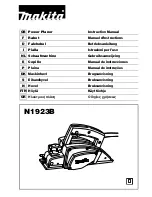
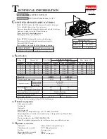
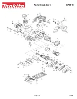
N1923B
Brand: Makita Pages: 60
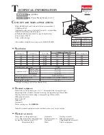
KP0810
Brand: Makita Pages: 11
KP0810
Brand: Makita Pages: 3
KP0800
Brand: Makita Pages: 8
1912B
Brand: Makita Pages: 3
1911B
Brand: Makita Pages: 44
1900B
Brand: Makita Pages: 12
1902
Brand: Makita Pages: 2
KP312
Brand: Makita Pages: 3

XCH 6RF
Brand: Jensen Pages: 8

CD-26
Brand: Jensen Pages: 7

ALIO CD-DAB
Brand: Tangent Pages: 144

KH 2262
Brand: E-Bench Pages: 12

CD50 mk2
Brand: Creek Audio Pages: 12

R3903663
Brand: Volvo Pages: 11

AZ1021
Brand: Philips Pages: 2

Soundmachine AZ3014
Brand: Philips Pages: 2


