background image

Tecumseh  H.P. Engine LH1SA-1 
Craftsman Snow Thrower Model .0

!


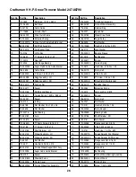
Ref. No. Part No.

Description

0

33329E

Electric Starter 110 Volt (optional)

1

33451

Dust Cover 

2

33842

Retainer Ring

3

33430

Spring Retainer

4

33431

Anti-Drift Spring

5A

37050

Gear & Nut (Incl. 2)

6

35449

Drive End Cap Assembly

7

35450

“O” Ring

8

35915

Armature

9

35451B

Housing Assembly

10

35452A

Brush Card Assembly

11

35911

Thrust Washer

13

590500

Thrust Washer

14

33441

Ground Screw

15

35453

Commutator End Cap Assembly 

16

35454

Switch Box Ass’y.

22

35455

Case Bolt

23

35456

Ground Screw

26

650819

Screw, 6-32 X 2-1/2”

26

651032

Screw, 12-16 x 5/8”

29

32450B

Extension Cord (10’6”)

30

30063

Screw, Torx T-30, 1/4-20 X 1/2”

31

650820

Screw, 1/4-20 X 1/2” 

Summary of Contents for 247.88790

Page 1: ... www sears com craftsman CAUTION Before using this product read this manual and follow all safety rules and operating instructions Operator s Manual 9 Horse Power SNOW THROWER Model No 247 88790 SAFETY ASSEMBLY OPERATION MAINTENANCE PARTS LIST 06 13 2006 FORM NO 769 02587 ...

Page 2: ...ew Craftsman product is designed and manufactured for years of dependable opera tion But like all products it may require repair from time to time That s when having a Repair Protection Agreement can save you money and aggravation Here s what s included in the Agreement Expert service by our 12 000 professional repair specialists Unlimited service and no charge for parts and labor on all covered r...

Page 3: ... assembly Shut off engine and remain behind handles until all moving parts have stopped before using the clean out tool to clear the chute assembly HUTE LEAN OUT 4OOL WARNING This symbol points out important safety instruc tions which if not followed could endanger the personal safety and or property of yourself and others Read and follow all instructions in this manual before attempting to operat...

Page 4: ...ne and machine adjust to outdoor temperature before starting to clear snow 9 To avoid personal injury or property damage use extreme care in handling gasoline Gasoline is extremely flammable and the vapors are explosive Serious personal injury can occur when gasoline is spilled on yourself or your clothes which can ignite Wash your skin and change clothes immediately a Use only an approved gasolin...

Page 5: ...gs Always use the clean out tool provided to unclog the discharge opening Do not unclog chute assembly while engine is running Shut off engine and remain behind handles until all moving parts have stopped before unclogging 19 Use only attachments and accessories approved by the manufacturer e g wheel weights tire chains cabs etc 20 If situations occur which are not covered in this manual use care ...

Page 6: ...arton has been completely emptied before discarding it Setting up Snow Thrower 1 Observe the lower rear area of the snow thrower to be sure both cables are aligned with roller guides before pivoting the handle upward See Figure 1 2 Secure the handle by tightening the plastic knob located on both the left and right sides of the handle Remove and discard any rubber bands if present They are for pack...

Page 7: ...ing and secure chute control assembly to chute support bracket with clevis pin and cotter pin removed earlier See Figure 5 6 Finish securing chute control assembly to chute support bracket with wing nut and hex screw removed earlier See Figure 6 7 Check that all cables are properly routed through the cable guide on top of the engine See Figure 7 Figure 7 ...

Page 8: ...ower on gravel as loose gravel can be easily picked up and thrown by the auger causing personal injury or damage to the snow thrower The snow thrower skid shoes are adjusted at the factory for normal operation If you have to operate the snow thrower on gravel keep the skid shoe in the highest position for maximum clearance between the ground and the shave plate Refer to Skid Shoes on page 18 Tire ...

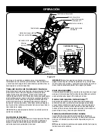
Page 9: ...owest and position six 6 is the fastest Reverse There are two reverse R speeds One 1 is the slower and two 2 is the faster Electric Starter Button Pressing the electric starter button engages the engine s electric starter when plugged into a 120V power source Choke Control The choke control is found on the rear of the engine and is activated by rotating the knob clockwise Activating the choke cont...

Page 10: ...ngine Doing so may cause it to break Four Way Chute Control The chute directional control is located on the left side of the dash panel To change the direction in which snow is thrown squeeze the button on the joy stick and pivot the joy stick to the right or to the left To change the angle distance which snow is thrown pivot the joy stick forward or backward Clean Out Tool WARNING Never use your ...

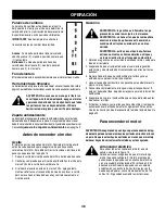
Page 11: ...e it snaps into place Do not attempt to turn the key NOTE The engine cannot start without the key is fully inserted into the ignition switch Electric Starter 1 Determine that your home s wiring is a three wire grounded system Ask a licensed electrician if you are not certain WARNING The optional electric starter is equipped with a grounded three wire power cord and plug and is designed to operate ...

Page 12: ...inst the handle and the augers will turn Release it and the augers will stop 3 Squeeze the drive control against the handle the snow thrower will move Release it and drive motion will stop IMPORTANT NEVER reposition the shift lever change speeds or direction of travel without first releasing the drive control and bringing the snow thrower to a complete stop Doing so will result in premature wear t...

Page 13: ...re putting back the wheels 4 Auger Shaft At least once a season remove the shear pins on auger shaft Spray lubricant inside shaft around the spacers Also lubricate the flange bearings found at either end of the shaft See Figure 10 Check V Belts Follow instructions below to check the condition of the drive belts every 50 hours of operation 1 Remove the plastic belt cover on the front of the engine ...

Page 14: ...ap to 030 0 76mm if necessary NOTE A resistor spark plug must be used for replacement Contact a Sears Parts and Repair Center for a replacement spark plug Check Augers The augers are secured to the spiral shaft with two shear pins and cotter pins See Figure 10 If you hit a foreign object or ice jam the snow thrower is designed so that the pins may shear 1 If the augers do not turn check to see if ...

Page 15: ...tapping screws from the frame cover underneath the snow thrower and move the frame cover away See Figure 14 Auger Belt 1 Roll auger belt off the pulley as shown in Figure 15 2 a Turn the shoulder screw a half a turn and slide it out of the mounting bracket See Figure 16 b Unhook spring to release tension on the auger belt See Figure 16 3 Remove old belt and replace with new belt wrapping it around...

Page 16: ...round the engine pulley from where the old belt was removed Once the belt is firmly placed on the pulleys make sure to remove the screwdriver from the idler 4 Re install auger belt on the engine pulley 5 Re attach frame cover on the snow thrower housing and put the equipment back to operating position Re attach belt cover with two self tapping screws removed earlier Friction Wheel Rubber NOTE Seve...

Page 17: ...index bracket See Figure 20 3 Pivot the bracket downward to take up slack in the cable 4 Retighten the hex nut 5 Check for correct adjustment before operating the snow thrower Chute Control Once a season or every 25 hours of operation whichever is earlier check whether the four way chute control cables have slackened If the chute does not rotate fully or its pitch cannot be moved up or down the ch...

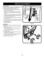
Page 18: ...ny of the above tests failed the drive cable is in need of adjust ment Proceed as follows 5 Loosen the lower hex nut on the drive cable bracket See Figure 22 6 Position the bracket upward to provide more slack or downward to increase cable tension 7 Retighten the lower hex nut Skid Shoes The space between the skid shoes and the ground can be adjusted See Figure 23 For close snow removal on a smoot...

Page 19: ...erm Storage To avoid engine problems the fuel system should be emptied before storage for 30 days or longer WARNING Fuel left in engine during warm weather deteriorates and will cause serious starting prob lems 1 Run the engine until the fuel tank is empty and it stops due to lack of fuel Do not attempt to pour fuel from the engine WARNING Never use engine or carburetor cleaning products in the fu...

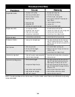
Page 20: ...ts 2 Replace drive belt 1 Drive control cable in need of adjustment 2 Drive belt loose or damaged Excessive Vibration 1 Loose parts or damaged auger Unit fails to discharge snow 1 Stop engine immediately and disconnect spark plug wire Clean chute assembly and inside of auger housing with clean out tool or a stick 2 Stop engine immediately and disconnect spark plug wire Remove object from auger wit...

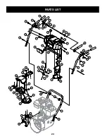
Page 21: ...21 PARTS LIST 2 9 23 12 24 43 45 44 44 45 39 37 32 36 30 29 28 6 7 27 4 5 3 2 19 15 20 11 13 12 14 55 18 1 31 34 8 35 46 42 50 51 25 26 12 2 24 33 50 41 51 48 54 10 56 49 52 53 47 22 38 17 20 21 16 40 ...

Page 22: ...e 23 790 00091 Slide Shoe 24 710 0451 Carriage Bolt 25 790 00118 Shave Plate 26 684 04057 Impeller Assembly 27 717 04126 Worm Shaft 28 721 0327 Oil Seal Ref No Part No Description 29 741 0662 Flange Bearing 30 718 04071 Thrust Collar 31 741 0663 Flange Bearing 32 710 0642 TT Screw 1 4 20 x 0 75 33 790 00087A Bearing Housing 34 721 0325 Plug 35 736 3084 Flat Washer 36 715 04021 Dowel Pin 37 684 041...

Page 23: ...RTS LIST 41 40 42 13 12 11 20 19 5 8 17 3 21 6 4 6 7 8 44 11 1 16 15 26 38 39 43 37 50 51 36 22 25 31 24 33 48 45 47 55 56 57 47 23 30 46 63 23 28 29 34 35 14 53 27 10 18 32 A A 2 54 58 62 61 59 14 49 60 52 ...

Page 24: ... Selector Cable 30 736 0463 Flat Washer 25 x 630 x 0515 31 710 0224 Screw 10 16 x 500 32 710 0606 Hex Screw 1 4 20 x 1 50 Ref No Part No Description 33 731 04427A Upper Chute 34 790 00155 Joystick Bracket 35 710 04187 Hi Lo Screw 1 4 15 x 0 5 36 984 04116B 4 Way Chute Control Assembly 37 749 04142 Upper Handle LH 38 710 04326 Screw 8 16 x 0 50 39 732 04219A Clutch Lock Spring 40 731 04913 Steering...

Page 25: ...16 2 15 13 13 69 12 69 4 67 28 1 27 24 22 12 40 40 42 82 81 81 80 79 22 9 21 43 24 8 23 A A 44 45 17 6 26 25 41 42 15 25 68 37 60 35 61 57 65 77 78 76 1 72 64 63 71 63 48 47 1 36 16 5 1 39 59 34 38 73 75 20 74 66 46 62 55 56 55 52 51 50 54 49 59 58 19 53 18 1 29 11 3 ...

Page 26: ...37 748 0190 Spacer 38 738 04184A Shoulder Screw 39 790 00226 Frame Cover 40 656 04025A Friction Wheel Disc Assembly Ref No Part No Description 41 918 04322 Drive Shaft Assembly 42 684 04159 Friction Wheel Assembly 43 716 0136 Retainer Ring 44 726 0221 Speed Nut 45 790 00183 Wheel Drive Frame 46 756 04109 Auger Pulley 47 736 0505 Flat Washer 48 710 1245B Hex Bolt 5 16 24 x 0 875 49 736 0119 Lock Wa...

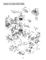
Page 27: ...27 Tecumseh 9 H P Engine LH318SA 156554 Craftsman Snow Thrower Model 247 88790 ...

Page 28: ...nkshaft Bushing 72 27642 Oil Drain Plug 75 35319 Oil Seal 76 28926 Camshaft Seal 80 37587 Governor Shaft Ref No Part No Description 81 651080 Washer 82 37588 Governor Gear Ass y Incl 81 83 30588A Governor Spool 84 29193 Retaining Ring 86 650833 Screw 1 4 20 x 1 3 16 87 650832 Screw 1 4 20 x 1 11 16 89 32589 Flywheel Key 90 611093 Flywheel W Ring Gear 92 650880 Lock Washer 93 650881 Flywheel Nut 10...

Page 29: ...0 Fuel Line Clamp 298 650665 Screw 1 4 15 x 7 8 300 34186A Fuel Tank Incl 292 301 Ref No Part No Description 301 35355 Fuel Cap 311 35942 Oil Fill Plug 314 650873 Screw 1 4 20 x 3 4 315 611111 Alternator Coil 18 Watt Incl 322 323 322 611117 Connector Body 323 611118 Terminal 325 29443 Wire Clip 328 35062 Ignition Keys 329 610973 Terminal 335 36547 Carburetor Cover 336 650765 Screw 10 32 x 1 2 338 ...

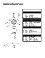
Page 30: ...Spring 16 632164 Fuel Fitting 17 651025 Throttle Crack Screw Idle Speed Screw 18 630766 Tension Spring 20 640027 Idle Restrictor Screw 20A 640200 Idle Restrictor Screw Cap 25 631867 Float Bowl no drain 27 631024 Float Shaft 28 632802 Float Plastic 29 631028 Float Bowl O Ring 30 631021A Inlet Needle Seat Clip Incl 31 31 631022 Spring Clip 36 640113 Nozzle Tube 37 632547 O Ring Main Nozzle Tube 40 6...

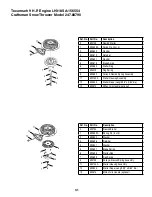
Page 31: ...Rewind Spring Assembly 11 590750A Starter Housing Assembly 12 590535 Starter Rope Length 98 x 9 64 dia 13 590574 Mitten Grip Handle optional Ref No Part No Description 0 590733 Rewind Starter 1 590599A Spring Pin Incl 4 2 590600 Washer 3 590696 Retainer 4 590601 Washer 5 590697 Brake Spring 6 590698 Starter Dog 7 590699 Dog Spring 8 590709 Pulley Rewind Spring Assembly 11 590734A Starter Housing A...

Page 32: ...Nut Incl 2 6 35449 Drive End Cap Assembly 7 35450 O Ring 8 35915 Armature 9 35451B Housing Assembly 10 35452A Brush Card Assembly 11 35911 Thrust Washer 13 590500 Thrust Washer 14 33441 Ground Screw 15 35453 Commutator End Cap Assembly 16 35454 Switch Box Ass y 22 35455 Case Bolt 23 35456 Ground Screw 26 650819 Screw 6 32 X 2 1 2 26 651032 Screw 12 16 x 5 8 29 32450B Extension Cord 10 6 30 30063 S...

Page 33: ...anty Defects are judged on normal engine performance The warranty is not related to an in use emission test Sears Emission Control Defects Warranty Provisions The following are specific provisions relative to your Emission Control Defects Warranty Coverage It is in addition to the Sears engine warranty for non regulated engines found in the Operating and Maintenance Instructions 1 Warranted Parts ...

Page 34: ...xample a typical walk behind lawn mower is used 20 to 25 hours per year Therefore the Emissions Durability Period of an engine with an intermediate rating would equate to 10 to 12 years The Air Index is a calculated number describing the relative level of emissions for a specific engine family The lower the Air Index the cleaner the engine This information is displayed in graphical form on the emi...

Page 35: ...pport from a Sears technician on products requiring in home repair plus convenient repair scheduling Purchase a Repair Protection Agreement now and protect yourself from unexpected hassle and expense Once you purchase the Agreement a simple phone call is all that it takes for you to schedule service You can call anytime day or night or schedule a service appointment online Sears has over 12 000 pr...

Page 36: ... craftsman PRECAUCIÓN antes de utilizar este producto lea este manual y siga todas las reglas de seguridad y las instrucciones de funcionamiento Manual del operador 9 caballos de fuerza MÁQUINA QUITANIEVE Número de modelo 247 88790 SEGURIDAD MONTAJE OPERACIÓN MANTENIMIENTO LISTADO DE PIEZAS ...

Page 37: ... años de funcionamiento confiable Pero como todos los productos a veces puede requerir de reparaciones Es en ese momento cuando el disponer de un acuerdo de protección para reparaciones le puede ahorrar dinero y problemas A continuación se detallan los puntos incluidos en el acuerdo Servicio experto prestado por nuestros 12 000 especialistas en reparaciones profesionales Servicio ilimitado sin car...

Page 38: ...de operar la máquina quitanieve ADVERTENCIA Never use your hands to clear a nunca use sus manos para liberar un montaje de canal tapado Apague el motor y permanezca detrás de las manijas hasta que todas las partes móviles se hayan detenido antes de utilizar la herramienta de limpieza para limpiar el montaje del cana ERRAMIENTA DE LIMPIEZA DEL CANAL WARNING This symbol points out important safety i...

Page 39: ...motor y la máquina se adapten a la temperatura exterior antes de comenzar a sacar la nieve 9 Paraevitarlesionespersonalesodañosmaterialesseasumamentecuidadosoal manipularlagasolina Lagasolinaesaltamenteinflamableysusvaporespuedencausar explosiones Sepuedelesionargravementesiderramagasolinasobreustedosobrela ropayaquesepuedeprenderfuego Láveselapielycámbiesederopadeinmediato a Utilice sólo recipien...

Page 40: ...ódicamente que funcionen de forma adecuada Remítase a las secciones de mantenimiento y ajuste de este manual 2 Antes de realizar la limpieza reparar o revisar la máquina desengrane todas las palancas de control y detenga el motor Espere a que la barrena motor se detenga por completo Desconecte el cable de la bujía y póngalo de manera que haga masa contra el motor para evitar que se encienda de man...

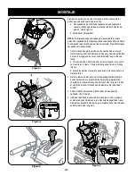
Page 41: ...pletamente la caja antes de tirarla a Tire hacia arriba y hacia atrás de la manija superior tal y como se muestra en la figura 1 Alinee la manija superior con la manija inferior b Apriete las perillas manuales que sujetan la manija superior a la manija inferior 2 Retire la tuerca de mariposa y el tornillo hexagonal del montaje de control del canal y el pasador de horquilla y el pasador de chaveta ...

Page 42: ...2 Detenga el motor moviendo el estrangulador a la posición de parada 3 Quite la herramienta de limpieza del pasador de ensamblado Vea la figura 7 4 Use el extremo con forma de pala de la herramienta de limpieza para eliminar la nieve y el hielo existentes en el montaje del canal 5 Vuelva a ajustar la herramienta de limpieza al pasador de ens amblado ubicado en la parte posterior de la caja de la b...

Page 43: ...mente en la sección Operación Asegúrese de que del estrangulador está ajustado en posición FAST rápida 4 Parado en la posición del operador detrás de la máquina quita nieve engrane la barrena 5 Deje la barrena engranada durante aproximadamente diez 10 segundos antes de soltar el control de la barrena Repita esta operación varias veces 6 Con el motor funcionando en posición rápida y el control de l...

Page 44: ...Para ajustar las zapatas antideslizantes afloje las cuatro tuercas de seguridad y los pernos de carro y mueva las zapatas antidesli zantes hasta la posición deseada Vea la figura 11 2 Compruebe que toda la superficie inferior de las zapatas antidesli zantes esté contra el suelo para evitar un desgaste desparejo de las mismas 3 Ajuste las tuercas y los pernos IMPORTANTE no se recomienda que opere e...

Page 45: ...control de la transmisión antes de cambiar las velocidades Control de la barrena El control de la barrena está ubicado en la manija izquierda Presione el control de la barrena para engranar las barrenas Suéltelo para detener la acción de liberación de nieve También debe soltar el control de transmisión para detener la barrenar IMPORTANTE consulte la prueba de control de la barrena en la página 8 a...

Page 46: ...arilla del nivel aceite en el llenado de aceite y controle nuevamente el nivel de aceite Gasolina ADVERTENCIA la gasolina es inflamable tenga precaución cuando la manipule o la almacene ADVERTENCIA no llene el tanque de combustible mientras la máquina quitanieve está en marcha cuando está caliente o cuando está en un área cerrada ADVERTENCIA evite que su máquina quitanieve entre en contacto con ll...

Page 47: ...cador y rote suavemente el obturador a posición OFF apagado Si el motor falla rote el obturador inmediatamente a posición FULL y luego gradualmente a OFF 12 Primero desconecte el cable de alimentación del receptáculo y luego desconéctelo de la caja del interruptor en el motor 13 Deje que el motor se enfríe por algunos minutos ya que el motor no alcanzará la potencia total hasta lograr la temperatu...

Page 48: ...o de quitar la nieve 3 Suelte el control de la barrena el mecanismo de bloqueo debe mantener engranado el control de la barrena hasta que se suelte el control de la transmisión 4 Suelte el control de la transmisión para detener tanto las barrenas como la transmisión de las ruedas Para detener la barrena debe soltar ambas palancas Procedimiento para quitar la nieve PRECAUCIÓN Revise la zona que des...

Page 49: ...ar las ruedas 5 Eje de la barrena Al menos una vez por temporada quite los pasadores de cuchilla del eje de la barrena Rocíe lubricante al interior del eje alrededor de los separadores Asimismo lubrique los cojinetes bridados que se encuentran en ambos extremos del eje Vea la figura 13 Compruebe las correas en V Siga las instrucciones a continuación para verificar el estado de las correas de trans...

Page 50: ...ados atorados por depósitos o la porcelana está rota 4 Controle el espacio del electrodo con un calibrador de separacio nes y ajuste dicho espacio a 0 030 pulg 0 76 mm si es necesario NOTA para el reemplazo se debe utilizar una bujía de resistor Contacte con un centro de partes y reparación Sears para una bujía de repuesto Control de las barreras Las barrenas están ajustadas al eje espiral con dos...

Page 51: ...a del marco ubicada debajo de la máquina quitanieve y mueva hacia afuera dicha cubierta Vea la figura 18 Correa de la barrena 1 Saque la correa de la barrena fuera de la polea tal y como se muestra en la figura 19 2 a Realice medio giro del tornillo con reborde y deslícelo fuera de la ménsula de montaje Vea la figura 20 b Desenganche el resorte para liberar la tensión de la correa de la barrena Ve...

Page 52: ... de donde se retiró la correa vieja Cuando la correa esté firmemente situada en las poleas asegúrese de quitar el destornillador de la polea loca 4 Vuelva a instalar la correa de la barrena en la polea del motor 5 Vuelva a colocar la cubierta del marco en la caja de la máquina quitanieve y vuelva a situar el equipo en posición de operación Vuelva a instalar la cubierta de la correa con los dos tor...

Page 53: ...a reducir el juego del cable 4 Vuelva a apretar la tuerca hexagonal 5 Antes de poner en funcionamiento la máquina quitanieve verifique que los ajustes sean correctos Control del canal Una vez por temporada o cada 25 horas de operación lo que suceda antes revise si los cables del controlTM del canal de cuatro direc ciones se han aflojado Si el canal no gira completamente o si no puede ajustarse la ...

Page 54: ...la transmisión en todas las posiciones de la palanca de cambios 3 Con el control de la transmisión engranado la rueda de fricción debe hacer contacto con la placa de la transmisión Vea la figura 21 4 Si es necesario realizar ajustes afloje la tuerca hexagonal inferior del soporte de posicionamiento del cable de la transmisión y haga girar dicho soporte hacia arriba o hacia abajo según sea necesari...

Page 55: ... de un recipiente aprobado en un lugar exterior lejos de todo tipo de fuego Compruebe que el motor esté frío No fume El combustible que se deje en el motor se deteriora cuando el clima es cálido y causa graves problemas de encendido 1 Ponga el motor en marcha hasta vaciar el depósito de combustible y hasta que el motor se detenga debido a la falta de combustible NOTA El uso de estabilizadores de c...

Page 56: ... Consulte la sección de ajustes 2 Reemplace la correa de la transmisión 1 El cable del control de transmisión necesita un ajuste 2 Lacorreadetransmisiónestáflojaodañada Demasiada vibración 1 Hay piezas que están flojas o la barrena está dañada La unidad no descarga la nieve 1 Detenga el motor de inmediato y desconecte el cable de la bujía Limpie el montaje del canal y el interior de la caja de la ...

Page 57: ...n de acuerdo con el funcionamiento normal de un motor La garantía no está relacionada con una prueba de emisiones en uso Disposiciones de la garantía Sears para defectos en el control de emisiones Las siguientes son disposiciones específicas relacionadas con la cobertura de la garantía para defectos en el control de emisiones Es un añadido a la garantía de motor Sears para motores no regulados que...

Page 58: ...ivo Ayuda rápida por teléfono asistencia telefónica a cargo de un técnico de Sears para los productos que requieren reparación a domicilio además de una programación conveniente para la reparación Una vez adquirido el Acuerdo puede programar el servicio con tan sólo realizar una llamada telefónica Puede llamar en cualquier momento del día o de la noche o programar un servicio en línea Sears dispon...

Page 59: ...NOTAS 59 ...

Page 60: ...essional installation of home appliances and items like garage door openers and water heaters 1 800 4 MY HOME 1 800 469 4663 Call anytime day or night U S A and Canada www sears com www sears ca Our Home For repair of carry in items like vacuums lawn equipment and electronics call or go on line for the location of your nearest Sears Parts Repair Center 1 800 488 1222 Call anytime day or night U S ...

Reviews: