background image

Summary of Contents for 152.217050

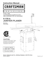
Page 1: ...ode_ No 152 217050 C S FOR YOUR OWN SAFETY Read and foUlow all of the Safety and Operating Instructions before Operating this Table Saw Customer Helpline 1 800 897 7709 PRease have your Model No and SedaR No availabUe Sears Roebuck and Co Hoffman Estates JL 60179 U S A Part No 0R92216 EspaSoU pg 33 ...

Page 2: ... gives you specific legal rights and you may also have other rights which vary from state to state Sears Roebuck and Co Dept 817 WA Hoffman Estates IL 60179 Motor Continuous Duty HP Volts Hertz RPM Infeed table dimension Outfeed table dimension Fence Tilt Fence Positive Stops Cutterhead RPM 1 1 2 120 6O 3450 R P M no load speed 22 inch 22 3 8 inch 45 Degrees in and out 90 45 Degrees in and out 500...

Page 3: ...RCE THE TOOL to perform an opera tion for which it was not designed It will do a safer and higher quality job by only performing operations for which the tool was intended 8 WEAR PROPER CLOTHING DO NOT wear loose clothing gloves neckties or jewelry These items can get caught in the machine during operations and pull the operator into the moving parts Users must wear a protective cover on their hai...

Page 4: ...p and water 27 USE A PROPER EXTENSION CORD IN GOOD CONDITION When using an extension cord be sure to use one heavy enough to carry the current your product will draw The table to the right shows the correct size to use depending on cord length and nameplate amperage rating if in doubt use the next heavier gauge The smaller the gauge number the larger diameter of the extension cord if in doubt of t...

Page 5: ... USE ONLY A 3 WIRE EXTENSION CORD THAT HAS A 3 PRONG GROUNDING PLUG AND A 3 POLE RECEPTACLE THAT ACCEPTS THE TOOL S PLUG REPLACE A DAMAGED OR WORN CORD IMMED iATELY FOR GROUNDED CORD CONNECTED MACHINES INTENDED FOR USE ON A SUPPLY CIRCUIT HAVING A NOMINAL RATING LESS THAN 150 VOLTS This tool is intended for use on a circuit that has an electrical receptacle as shown in FIGURE 1A FIGURE 1A shows a ...

Page 6: ... 7 8 9 10 11 12 13 14 15 16 17 18 KEEP cutterhead knives sharp and free of all rust and pitch BEFORE starting machine check cutterhead guard to make sure it is not damaged and operates freely ALWAYS make sure exposed cutterhead behind the fence is guarded especially when jointing near the edge NEVER perform jointing or planing operations with the cutterhead guard removed MAKE CERTAIN the infeed an...

Page 7: ...ing dustto getinto yourmouth oreyes orlayonyourskinmaypro moteabsorption ofharmful material Always use properly fittingNIOSH OSHA approved respiratory protection appropriate forthedustexposure and washexposed areawithsoapandwater 26 ADDITIONAL INFORMATION regarding thesafe andproper operation of thisproduct isavailable from Power Toolinstitute 1300Summer Avenue Cleveland OH44115 2851 www powertool...

Page 8: ...ply a good quality automotive wax to any unpainted surfaces Make sure to buff out the wax before assembly Compare the parts to figures 2 1 2 2 and 2 3 Verify that all items are accounted for before dis carding the shipping carton if there are any missing parts call Customer Helpline 1 800 897 7709 Please have your part number ready Part numbers can be found in the Parts List section of your instru...

Page 9: ...d screw 3 8 16 x 1 4 25 Carriage head screw 5 16o18 x 1ol 8 4 26 Fiat washer MIO 4 27 Hex nut 5 16 18 4 28 Hex head screw M6 x 12mm 16 29 Fiat washer M6 16 30 Hex nut M6 16 31 Hex socket head screw M8 x 30mm 2 32 Fiat washer M8 2 33 Hex nut M8 2 34 Lock washer MIO 3 35 Fiat washer MIO 3 36 Hex nut MIO 3 37 Round head flange screw 10o24 x 3 8 35 not shown 38 Hex wrench 2 Smm not shown 39 Hex wrench...

Page 10: ... 7 Cutterhead guard 8 Hnfeed tame 9 Hnfeed tame height adjustment handHe 10 Depth of Cut scaHe 11 Push Mocks 12 Push Mock hoHder 13 EncHosed stand 14 Leveling feet 15 Dust Chute Port Note Dust Chute Port is onHyto be assembHed if a dust coHHector is to be used with this Jointer PHaner 16 Outfeed tame height adjustment handHe 10 ...

Page 11: ...tom of the left side panel assembly The bottom of the left side panel is 13 inches from the bottom of the square cut out as shown in Figure 4 1 3 Position the stand assembly G upright and assem ble the right side panel assembly H to the bottom plate C using four M6 x 12mm hex head screws M6 fiat washers and M6 hex nuts Do not com pletely tighten hardware Note Make sure to posi tion the power cord ...

Page 12: ...ws C in the motor pulley are backed off so that the motor pulley can slide onto the motor shaft See Figure 5 1 2 AHgn the 5mm x 5mm x 30mm square key aUready in the motor shaft with the keyway in the pufley SHde the motor pufley onto the motor shaft until the pufley is flush with the end of the motor shaft as shown in Figure 5 1 Tighten both set screws C at this time Fig 5 2 C D X H 10 Thread the ...

Page 13: ... them in haft way 7 SHde sbts K of the push Mock holder L down onto the two screws J in the side panel 8 Attach the arm M of the push Mock holder to the hob N in the side pane with one 10 24 x 3 8 round head flange screw 9 Securely tighten a stand hardware except for motor mounting hardware at this time JO NTER PLANER ASSEMBLY DO NOT assemble the Jointer Haner until you are sure the power switch i...

Page 14: ...ill need to be moved up higher on the dust chute F to allow belt around both pulleys See Figure 8 1 Tension the belt by moving the motor down the dust chute Note Proper tension is achieved when there is approximately 1 deflection at the center of the belt span using light finger pressure After achieving proper tension check again for proper pulley alignment Then tighten motor mounting hardware sec...

Page 15: ...e fence brackets Fig 10 2 K 5 Once both fence brackets have been placed onto the front support bracket pins hold the fence bevel assembly upright as shown in Figure 10 3 Assemble the fence brackets to the fence with the four M8 x 14mm hex socket head screws I and fiat washers J removed in STEP 3 Do not com pletely tighten hardware Note Make sure the fence brackets stay engaged with the front suppo...

Page 16: ...ss movement turn Nylock hex nut clockwise To make locking with more move ment turn Nylock hex nut counterclockwise Check that the fence locks and unlocks by rotating the cam lock handle Make certain that the fence assembly can move across the table width without excessive drag from the locking mechanism Fig 10 8 9 Carefully lay the fence assembly V which includes the fence bevel assembly B onto th...

Page 17: ...uard to the infeed tame C by piacing the post A through the hob in the infeed tame 3 Turn knob D on underside of the hob 1 2 turn to provide tension on the return spring This spring allows the guard to return over the cutterhead after the cut has been made 4 Align the slot in the post with the spring then insert post 5 Check that the guard returns completely if it does not remove the guard and add...

Page 18: ...paddle C or lift the paddle and press direct ly on the red OFF button D See Figure 13 1 and 13 2 LOCKING SWITCH IN THE OFF PosmoN CHILDPROOF THE WORKSHOP AREA by removing switch keys unplugging tools from the electrical recep tacles and using padlocks Fig 13 2 DO NOT expose the Jointer Haner to rain or operate it in damp locations MAKE SURE all parts have been assembled correctly and are in workin...

Page 19: ...nce or adjustments 1 To raise or lower the infeed table loosen the infeed table lock handle A To loosen handle turn counterclockwise to tighten turn handle clockwise See Figure 14 1 Fig 14 1 3 4 After the depth of cut is set tighten the infeed table lock handle A See Figure 14 1 The pointer C on the depth of cut scab D indicates the infeed table depth of cut See Figure 14 1 OUTFEED TABLE OPERATION...

Page 20: ...n cam handle Make sure the cutterhead guard D returns and rests against the fence If not see CUTTERHEAD GUARD ASSEMBLY section in assembly instruction for setup procedure TILTING THE FENCE Turn the power switch OFF and unplug the power cord from its power source prior to performing any mainte nance or adjustments The fence can tilt up to 45 degrees in or out The fence has positive stops at 45 degr...

Page 21: ... fence is set correctly and then tighten stop nut 45 Degree in Positive Stop Adjustment Fig 17 3 H 1 To set fence 45 degree in to the table surface first make sure the 90 degree stop knob A is pulled out See Figure 17o3 2 Loosen the bevel lock handle D and tilt the fence forward and against the 45 degree in positive stop screw H Note This positive stop screw does not touch the fence on the head si...

Page 22: ...luded CAUTION The knives are very sharp take extra care when working around them See Figure 18 2 With the straight edge on the outfeed table extend ing over center of the cutterhead turn one or both jack screws H with the 2 Smm hex wrench included clockwise to bring the knife up until it touches the straight edge Make sure to check the knife at both jack screw locations Make additional adjustments...

Page 23: ... sure the cutterhead A knife adjustment jack screws C knife locking bars F and knives D are clean and free of any gum or pitch See Figure 20ol 2 Replace knife adjustment jack screws into one cutterhead groove 3 Replace knife locking bar into same cutterhead groove 4 CAUTION To avoid cutting yourself take care when handling knives The knives are very sharp Replace new or re sharpened knife in cutte...

Page 24: ... motor Have a certified electrician make all electrical connec tions All local and state codes must be maintained The motor supplied with the Jointer PDner is a dual voltage 120 240 voit single phase motor The motor is wired from the factory for 120 voit operation To change to 240 voit operation for your Jointer Haner proceed with the following instructions It is also necessary to replace the 120 ...

Page 25: ...tection appropriate forthedustexposure andwashexposed areaswithsoapandwater Fig 22 1 Jointing and planing operations generate large amounts of wood chips and dust A dust collection system is rec ommended for your Jointer Planer Provided with your Jointer Planer is a dust chute port with a 4 diameter A 4 diameter dust collection hose and clamp not included can be connected direct to the Jointer Pla...

Page 26: ... to conduct routine main tenance to keep your table saw looking new Cleaning and waxing the cast iron surfaces on a regular main tenance schedule is recommended as follows To ctean and maintain the unpainted cast iron surfaces Apply a heavy coat of WD 40 onto the unpainted cast iron surface Use a fine steel wool pad to buff the unpainted cast iron Make sure to buff in a front to rear direction onl...

Page 27: ...in the ON position Have switch replaced Have motor replaced repaired NOTE 2 and 3 must be done by a qualified service technician Consult Sears Service Correct line voltage condition Adiust belt tension Reduce circuit load turn off other appliances Correct low line voltage condition Reduce load on motor Have correct fuses on circuit breakers installed Inspect terminals in motor for damaged insulati...

Page 28: ...ET SET SCREW M6 x 25mm 5 75 OR90279 26 OR90237 GIB 2 76 STD84 2 7 27 OR90238 PUSH BLOCK 2 77 OR90714 28 0R90239 HEX SQCKET SET SCREW M6 x 6ram 1 79 OR90283 29 0R90246 WAVE WASHER M8 1 80 0R90284 30 OR9024 BUTTON HEAD SCREW M6 x 12rnm 1 8 OR90285 31 STD85 006 FLAT WASHER M6 1 82 OR90286 33 OR90242 HANDWHEEL 1 83 OR90287 34 QR90243 KNOB 1 84 OR90288 35 OR90244 HANDLE SHAFT 1 85 OR90460 36 OR90245 CO...

Page 29: ... 1 2 4 4 1 4 1 1 2 1 1 1 1 1 2 2 1 1 1 2 2 1 1 1 1 1 4 1 2 2 KEY PART NO NO DESCRIPTION 155 STD840610 158 STD523710 159 STD833012 160 STD8406 0 161 STD851006 162 OR90338 163 OR92198 164 STD881010 165 STD541031 166 STD881006 167 STD8406 0 168 OR90339 169 STD8330 2 170 OR90340 179 OR90340 N A OR93462 N A OR90463 180 OR90347 181 OR93468 182 OR92203 183 OR92202 184 OR93483 189 OR90352 190 STD8330 2 19...

Page 30: ...6 1 8qN JOmNTER PLANER PARTS UST MODEL NO 152 217050 86 85 87 88 89 90 I 45 75 30 ...

Page 31: ...6 1 8qN JOINTER PLANER PARTS UST MODEL NO 152 217050 115 27 i 32 i33 131 35 i36 31 ...

Page 32: ...6 1 8qN JOmNTER PLANER PARTS UST MODEL NO 152 217050 184 221 _ 179 190 181 193 _ 197_ 214 212 213 211 32 ...

Page 33: ..._o 152 217050 m P C S PARA SU SEGURIDAD PERSONAL Lea y obedezca todas las lnstrucciones de Seguddad y Funcionamiento antes de accionar esta MacNmbradora Cepilladora Linea de Ayuda al Cliente 1 800 897 7709 Sirvase tenet listo su No de Modelo y No de Serie Sears Roebuck and Co Hoffman Estates JL 60179 U S A No de Pieza OR92216 33 ...

Page 34: ...ears Roebuck and Co Dept 817 WA Hoffman Estates IL 60179 Motor HP servicio continuo 1 1 2 Voltios 120 Hertzios 60 RPM 3450 R RM velocidad sin carga Dimensiones de la mesa de alimentaci6n Dimensiones de la mesa de avarice Gu a de corte Inclinaci6n de la Gu a Topes positivos de la Gu a RPM del Cabezal de Corte 22 pulg 22 3 8 pulg 29 1 2 x 4 1 2 pulg 45 grados dentro y fuera 90 45 grados dentro y fue...

Page 35: ...ayendolo hacia las piezas en movimiento El usuario debe Ilevar una cubierta protectiva sobre eI cabeIIo si tiene cabellera larga para impedir el contacto con cualquier pieza en movimiento 9 10 11 12 13 UTIUCE PROTECCION OCULAR S_EMPRE Cualquier herramienta mecanica puede expulsar escombros hacia los ojos durante las operaciones resultando en daflo ocular grave y permanente Los anteojos cotidianos ...

Page 36: ...protecci6n respiratoria aprobados por NIOSH OSHA con buen ajuste y apropiados para la exposici6n al polvo lave las zonas expuestas con jab6n y agua 27 UTIUCE UNA EXTENSION ELECTR_CA CORRECTA Y EN BUEN ESTADO Cuando vaya a hacer uso de una extensi6n etectrica aseg0rese de utilizar una que sea Io suficientemente fuerte como para transportar Ia corriente a ser utilizada por su herramienta La siguient...

Page 37: ...ENCHUFE DE CONEXJON A TIERRA DE TRES MACNOS Y RECEPTACULO DE TRES MACNOS QUE ACEPTE EL ENCNUFE DE LA NERRAMIENTA REPONGA UN CORDON DANADO OR GASTADO tNMEDJATAMENTE PARA LAS MAQU_NAS CONECTADAS A TJERRA Y CON CORDON DISENADAS PARA EL USO EN UN CIRCU_TO DE SUM_NtSTRO QUE D_SPONGA DE UNA CLASJFJCA C_ON NOMINAL MENOR A LOS 150 VOLTJOS Esta herramienta est4 disehada para el uso en un circuito que tiene...

Page 38: ...alificada 3 MANTENGA las cuchilIas del cabezal de corte afiladas y libres de moho y alquitrb n 4 ANTES de arrancar la maquina revise el protector det cabezal de corte para asegurarse de que no esta daRado y que funciona libremente 5 ASEGURESE de que eI cabezat de corte expuesto detrAs de la gu a este protegido especialmente durante la realizaci6n de operaciones de machimbrado cerca del borde 6 JAM...

Page 39: ...do con el polvo El permitir que el polvo penetre su boca u ojos o que permanezca sobre su piel podra promover la absorci6n de materiales nocivos Utilice siempre Ia protecci6n respiratoria aprobado por NIOSH OSHA debidamente ajustada y correcta para la exposici6n aI polvo lave la zona expuesta con agua y jab6n 26 Hay INFORMACtON ADICIONAL acerca de Ia operaci6n segura y correcta de este producto di...

Page 40: ...quier superficie sin pintar Aseg0rese de pulir la cera antes del ensamblaje Compare las piezas con Ias figuras 2 1 2 2 y 2 3 Compruebe que todos los art culos esten completos antes de descartar Jacaia de env o Si faltan piezas comun quese con la L nea de Ayuda at Cliente al 1 800 897 7709 S rvase tener listo su n0mero de pieza Los n0meros de pieza pueden Iocalizarse en la secci6n de la Lista de Pi...

Page 41: ... 8 16 x 1 pulg 4 25 TornilIo de cabeza de carrocerfa 5 16 18 x lq 8 pulg 4 26 Arandela plana M10 4 27 Tuerca hexagonal 5 16 18 4 28 Tuerca de cabeza hexagonal M6 x 12 mm 16 29 Arandela plana M6 16 30 Tuerca hexagonal M6 16 31 TornilIo de cabeza hueca hexagonal M8 x 30 mm 2 32 ArandeIa plana M8 2 33 Tuerca hexagonal M8 2 34 Arandela de cierre M10 3 35 Arandela plana M10 3 36 Tuerca hexagonal M10 3 ...

Page 42: ...ce directo 9 Agarradera de ajuste de altura de la mesa de avance directo 10 Escala de profundidad de corte 11 Bloques de empuje 12 Portador de bloque de empuje 13 Estante encerrado 14 Pies niveladores 15 Salida del Conducto de PoNe Aviso ei Puerto deI Conducto de Polvo s61o debe ensamblarse si se va a utilizar un recolector de polvo con esta Machimbradora Cepilladora 16 Agarradera de ajuste de alt...

Page 43: ... deI panel lateral izquierdo se encuentra 13 pu gadas desde el fondo del agujero cuadrado seg0n Io ilustrado en la Figura 4 1 Co oque el ensamblado del estante G en posici6n verti cal y monte el ensamblado deI panel lateral derecho H a a placa de fondo C utilizando pare el o cuatro torniF los de cabeza hexagonal M6 x 12 ram arande as planas M6 y tuercas hexagonales M6 No apriete el herramentaI com...

Page 44: ...de fijaci6n C en la polea del motor esten rebajados de tal manera que la polea del motor pueda deslizarse sobre el eje del motor Ver Ia Figura 5 1 Allnee Ia Ilave cuadrada de 5 mm x 5 mmx 30 mm que ya se encuentra en el eje del motor con la chaveta de la polea Deslice la polea deI motor sobre el eje del motor hasta que la polea quede pareja con el extremo deI eje del motor conforme a o ilustrado e...

Page 45: ...la Machimbradora Cepilladora Fig 6 1 A 1 2 Co oque la Machimbradora Cepilladora A sobre el estante B de manera que los tres gorrones situados per debajo de la base de Ia machimbradora queden alinea dos con las tres ranuras en la placa superior deI estante Ver la Figura 6 1 Afiance la machimbradora al estante con tres arandeIas planas M10 arandelas de cierre M10 y tuercas hexago nales M10 Aviso Se ...

Page 46: ...erse hacla arrlba a Io largo del conducto de polvo F para permitlr que Ia correa rodee ambas poleas Ver la Flgura 8 1 Tenslone Ia correa moviendo el motor hacla abajo a Io largo deI conducto de polvo Avlso La tensi6n correcta se obtlene cuando existe una defiexi6n de aproximada mente 1 pulg en el centro del tramo de la correa ejer ciendo presi6n Iigera con el dedo Luego de haber conseguldo Ia tens...

Page 47: ...do colo cados sobre los pasadores de los soportes de apoyo delanteros de la gufa sostenga el ensambIado de bise lado de la gufa en posici6n vertical seg0n se iIustra en la Figura 10 3 Monte los soportes de Ia gufa a la gufa con los cuatro tornillos de cabeza hueca hexagonal M8 x 14 mm I y las cuatro arandelas planas J que fueron quita dos en e PASO 3 No apriete e herramental completa mente Aviso A...

Page 48: ... Nytock en el sentido de las agujas del reloj Para realizar el enclava miento con mas movimiento gire Ia tuerca Nylock contra el sentido de las agujas de reloj 11 Revise que la gu a se enclave y desenclave girando la agarradera de cierre de levas Aseg0rese de que et ensamblado de la gu a pueda moverse a Io ancho de la mesa sin arrastre excesivo proveniente de mecanismo de enclavamiento Fig 10 8 g ...

Page 49: ...bezal de corte a Ia mesa de avance directo C cotocando el poste A a traves del agujero en la mesa de avance directo Gire la perilIa D en Ia cara inferior de agujero 1 2 de vuelta para tensionar e resorte de retorno Este resorte permite el retomo del protector sobre el cabezal de corte despues de que se haya reatizado el corte Alinee la ranura en el poste con el resorte y luego inserte el poste Rev...

Page 50: ...NCENDIDO APAGADO A esta situado en el poste sobre la mesa de avance directo Ver la Figura 13 1 2 3 Para encender Ia Machimbradora CepilIadora oprima el bot6n verde de ENCENDIDO B una mitad de pulgada Aviso Existe un distintivo de seguridad en el interruptor para asegurar que el interruptor sea oprimido completa mente antes de que pueda arrancar el motor Para apagar Ia Machimbradora CepilIadora opr...

Page 51: ...tido de las agujas del reloj Para apretarla gire la asidera en el sentido de las aguias del reloi Ver Figura 14 1 Fig 14 1 D 3 4 PRECAUCI6N LA PROFUNDIDAD DE CORTE DE 1 2 PULG SOLO SE UTIUZA EN LAS OPERACIONES DE CORTE DE ALEFRJZ Una vez fijada la profundidad de corte apriete la asidera de enclavamiento de la mesa de alimentaci6n A Ver Figura 14 1 El indicador C en la escala de profundidad de cort...

Page 52: ... inclinarse hasta 45 grados adentro o afuera La gufa dispone de topes positives a los 45 grades adentro y 90 y 45 grades afuera Ajuste de Parada de 90 Grados Positivos Fig 17 1 A B APAGUE el interruptor de energfa y desenchufe el cord6n de energfa de su fuente de energfa antes de realizar cualquier mantenimiento o ajuste Fig 16 1 A C B 7 Para deslizar Ia guia A a Io ancho de la machimbra dora aflo...

Page 53: ...jada correctamente y luego apriete la tuerca de parada A uste de Parada de 45 Grados Positivos hacia Adentro Fig 17 3 H 1 2 3 4 5 6 7 Para fijar Ia gu a a 45 grados hacia adentro contra Ia superficie de Ia mesa aseg0rese primero de que se haya extra do Ja perilla de parada de 90 grades A Vet Ja Figura 17 3 Afloje la agarradera de cierre de biselado D e incline Ia guia hacia adelante y contra el to...

Page 54: ...con elias Ver la Figura 18 2 Con la regla sobre Ia mesa de avarice de salida y extendiendose sobre e centre de cabeza de corte gire uno u ambos tornillos niveladores H con Ia Ilave hexa gonal de 2 5 mm incluida en el sentido de las aguias del reloj para elevar la cuchilla hasta que toque la regla Aseg0rese de revisar Ia cuchilla en ambas Iocalizaciones de los tornillos nivetadores Realice ajustes ...

Page 55: ...os tornillos niveladores C las varillas de enclavamiento de cuchillas F y las cuchilIas D est6 n limpias y libres de pegamento o alquitran Ver Figura 20 1 Reponga los tornillos niveladores de ajuste de cuchillas en una ranura de cabezal de corte 3 4 Reponga la varilla de enclavamiento de cuchillas en la misma ranura de cabezaI de corte PRECAUCJON Para evitar cortaduras tenga cuidado al maneiar Ias...

Page 56: ...antes de efectuar reparaciones al motor Haga que un electricista competente realice todas Ias conexiones etectricas Deben conservarse todos los c6digos locales y estatales El motor suministrado con Ia Machim bradora CepiIIadora es un motor monofasico de 120 240 voltios El motor viene cabbado de fabrica para e funciona miento a 120 voitios Para cambiar su Machimbradora Cepilladora al funcionamiento...

Page 57: ... exposici6n al polvo lave las zonas expuestas con agua y jab6n Las operaciones de machimbrado y cepillado generan grandes cantidades de astillas de madera y polvo Se recomienda el use de un sistema de recolecci6n de polvo con su machimbradora cepilIadora Se proporciona un puerto de conducto de polvo de 4 pulg en diametro con su machim bradora cepilladora Una manguera de recolecci6n de polvo de 4 p...

Page 58: ...acia atras solamente Un movimiento de pulido de Iado a lade podra percibirse sobre el hierro moldeado finamente rectificado come una lacra defecto o rayadura Vuelva a aplicar WD 40 y siga puliendo las superficies de hierro moldeado sin pintar hasta que se hayan eliminado las manchas u oxidaci6n Aseg0rese de utilizar el mismo sentido deI frente hacia atras en el pulido para evitar rayar o desmejora...

Page 59: ...usibles correctos en los disyuntores de circuitos 5 Inspecciones las terminaciones en el motor para al aislamiento dahado y los cables cortocircuitados y reemplacelos 1 Reponga repare el motor 2 Ajuste la tension del cintur6n 3 Reponga el capacitor 1 Reduzca la carga al motor 2 Limpie el polvo y restaure la circulaci6n normal del aire 3 Ajuste la tension de correa 1 Reduzca la cargo al motor 2 Ins...

Page 60: ...iiiiiiiiiiiiiiiiii iiiiiiiiiiiiiiiiiii iiiiiiiiiiiiiiiiiii iiiiiiiiiiiiiiiiiii iiiiiiiiiiiiiiiiiii iiiiiiiiiiiiiiiiiii iiiiiiiiiiiiiiiiiii iiiiiiiiiiiiiiiiiii iiiiiiiiiiiiiiiiiii iiiiiiiiiiiiiiiiiii iiiiiiiiiiiiiiiiiii iiiiiiiiiiiiiiiiiii iiiiiiiiiiiiiiiiiii iiiiiiiiiiiiiiiiiii iiiiiiiiiiiiiiiiiii iiiiiiiiiiiiiiiiiii iiiiiiiiiiiiiiiiiii iiiiiiiiiiiiiiiiiii iiiiiiiiiiiiiiiiiii iiiiiiiiiiiiiiiiiii i...

Reviews: