background image

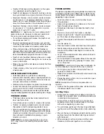
Do not use a 3-prong to 2-prong grounding adapter
unless permitted by local and national codes and
ordinances. (A 3-prong to 2-prong grounding adapter
is not permitted in Canada.)

Where a 3-prong to 2-prong grounding adapter is
permitted, the rigid green tab or terminal on the side
of the adapter must be securely connected to a
permanent electrical ground such as a properly
grounded water pipe, a properly grounded outlet box
or a properly grounded wire system.

Many cover plate screws, water pipes and outlet
boxes are not properly grounded. To ensure proper
ground, grounding means must be tested by a quali-
fied electrician.

EXTENSION CORDS

The use of any extension cord will cause some drop
in voltage and loss of power.

Wires of the extension cord must be of sufficient size
to carry the current and maintain adequate voltage.

Use the table to determine the minimum wire size
(A.W.G.) extension cord.

Use only 3-wire extension cords  having 3-prong
grounding type plugs and 3-pole receptacles which
accept the tool plug.

If the extension cord is worn, cut or damaged in any
way, replace it  immediately.

Extension Cord Length

Wire Size . . . . . . . . . . . . . . . . . . . . . . . . . . . . . . A.W.G.

Up to 25 ft. . . . . . . . . . . . . . . . . . . . . . . . . . . . . . . . . . 14

25 to 50 ft. . . . . . . . . . . . . . . . . . . . . . . . . . . . . . . . . . 12

NOTE:

Using extension cords over 50 ft. long is not

recommended.

MOTOR

The 120 Volt AC universal motor has the following
specifications:

Voltage . . . . . . . . . . . . . . . . . . . . . . . . . . . . . . . . . . . 120

Amperes. . . . . . . . . . . . . . . . . . . . . . . . . . . . . . . . . . . 12

Hertz . . . . . . . . . . . . . . . . . . . . . . . . . . . . . . . . . . . . . 60

Phase . . . . . . . . . . . . . . . . . . . . . . . . . . . . . . . . . . Single

Cutterhead RPM . . . . . . . . . . . . . . . . . . . . . . . . . . 9400

ELECTRICAL CONNECTIONS

WARNING: 

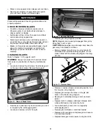
Make sure unit is turned off and discon-

nected from power source before inspecting any wiring.

The motor is assembled with an approved three con-
ductor cord to be used on 120 volts as indicated. The
power supply to the motor is controlled by a double
pole locking switch.

The power lines are connected directly to the switch.
The green ground line must remain securely fastened
to the frame to properly protect against electrical shock.

A manual reset overload protector is installed in line
with the power supply to the motor. If the planer is over-
loaded, the protector will break the circuit.

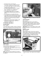
OPERATION

DESCRIPTION

Craftsman 12

1

/

2

planer finishes rough-cut lumber to

size and planes soft and hardwoods up to 6

thick and

12

1

/

2

wide. Wood feeds into two-blade cutterhead by

rubber infeed/outfeed rollers. Sturdy base construction,
granite table and four-post design permits smooth feed-
ing and virtually snipeless planing. Planer comes with
enclosed, universal ball bearing, 12 Amp motor with
overload protection. Motor has ON/OFF switch with
removable key to prevent accidental start-up. Unit fea-
tures easy hands-free replacement of blades for safety
and minimized downtime, top mounted roller for work-
piece return and built-in carrying handles for portability.
Planer takes cuts up to 

3

/

32

per pass at 26 feet per

minute. Inch height scale has graduations in 

1

/

16

incre-

ments, and metric height scale has graduations in 1mm
increments.

SPECIFICATIONS

Table Size . . . . . . . . . . . . . . . . . . . . . . . . . . 12

1

/

2

x 9

3

/

8

Extension Table Size . . . . . . . . . . . . . . . . . . 12

1

/

2

x 6

3

/

4

Base Size. . . . . . . . . . . . . . . . . . . . . . . . . . . . 21 x 12

1

/

2

Workpiece Width (max.). . . . . . . . . . . . . . . . . . . . . 12

1

/

2

Workpiece Thickness (max.) . . . . . . . . . . . . . . . . . . . 6

Maximum Depth of Cut . . . . . . . . . . . . . . . . . . . . . . . 

3

/

32

Cuts Per Minute . . . . . . . . . . . . . . . . . . . . . . . . . 18,800
Feed Rate . . . . . . . . . . . . . . . . . . . . . . . . . . . . . 26 FPM
Overall Dimensions . . . . . . . 23

1

/

2

W x 23

1

/

2

D x 19

H

Weight . . . . . . . . . . . . . . . . . . . . . . . . . . . . . . . . . 67 lbs
Shipping Weight . . . . . . . . . . . . . . . . . . . . . . . . . . 72 lbs

OPERATION SAFETY RULES

WARNING: 

For your own safety, read all of the

instructions and precautions before operating tool.

WARNING: 

Operation of any power tool can result in

foreign objects being thrown into eyes which can result
in severe eye damage. Always wear safety goggles
complying with United States ANSI Z87.1 (shown on
package) before commencing power tool operation.

CAUTION: 

Always observe the following safety pre-

cautions:

Know general power tool safety. Make sure all pre-
cautions are understood (see pages 2, 3, 5 and 6).

Whenever adjusting or replacing any parts on  planer,
turn switch OFF and remove plug from power source.

Make sure all guards are properly attached and
securely fastened.

Make sure all moving parts are free from interference.

Always wear eye protection or face shield.

Make sure blades are aligned and properly attached
to cutterhead.

Do not plug in planer unless switch is in off position.
After turning switch on, allow planer to come to full
speed before operating.

5

Summary of Contents for 124.33383

Page 1: ...offman Estates IL 60179 U S A www sears com craftsman 3 01 Operator s Manual 121 2 1 THICKNESS PLANER Model No CAUTION Read and follow all Safety Rules and Operating Instructions before First Use of this Product Keep this manual with tool ...

Page 2: ...apparel Do not wear loose clothing gloves neckties rings bracelets or other jewelry which may get caught in moving parts of machine Ǹ Wear protective hair covering tocontain long hair Ǹ Wear safety shoes with non slip soles Ǹ Wear safety glasses complying with United States ANSI Z87 1 Everyday glasses have only impact resistant lenses They are NOT safety glasses Ǹ Wear face mask or dust mask if op...

Page 3: ...fety Safety is a combination of operator common sense and alertness at all times when tool is being used WARNING Do not attempt to operate tool until it is completely assembled according to the instructions UNPACKING Refer to Figure 1 below Check for shipping damage If damage has occurred a claim must be filed with carrier Check for complete ness Immediately report missing parts to dealer IMPORTAN...

Page 4: ...of equipment grounding conductor can result in the risk of electrical shock Equipment should be grounded while in use to protect operator from electrical shock Check with a qualified electrician if you do not understand grounding instructions or if you are in doubt as to whether the tool is properly grounded This tool is equipped with an approved cord and a 3 prong grounding type plug see Figure 5...

Page 5: ...he protector will break the circuit OPERATION DESCRIPTION Craftsman 121 2 planer finishes rough cut lumber to size and planes soft and hardwoods up to 6 thick and 121 2 wide Wood feeds into two blade cutterhead by rubber infeed outfeed rollers Sturdy base construction granite table and four post design permits smooth feed ing and virtually snipeless planing Planer comes with enclosed universal bal...

Page 6: ...from unauthorized use by locking the switch To lock the switch Turn the switch to OFF position and disconnect plan er from power source Pull the key out The switch cannot be turned on with the key removed NOTE Should the key be removed from the switch at the ON position the switch can be turned off but cannot be turned on To replace key slide key into the slot on switch until it snaps CIRCUIT BREA...

Page 7: ...ood Sometimes grain will change directions in middle of board In such cases if possi ble cut board in middle before planing so grain direction is correct CAUTION Do not plane board which is less than 141 2 long force of cut could split board and cause kickback FEEDING WORK The planer is supplied with planing blades mounted in the cutterhead and infeed and outfeed rollers adjusted to the correct he...

Page 8: ... Remove blade guard Carefully turn cutterhead by hand towards you until it is stopped by the self engaging latch Loosen and remove six bolts from gib Remove gib using magnets provided NOTE Magnets can be easily disengaged from gib by tilting them to left or right CAUTION Blade edges are extremely sharp Keep fin gers away from blades at all times Blade is located in position by two pins Gently lift...

Page 9: ...t REPLACING V BELT Refer to Figures 14 and 15 pages 12 and 14 Inadequate tension in the V belt Fig 15 Key No 46 will cause the belt to slip from the motor pulley Fig 15 Key No 49 or drive pulley Fig 15 Key No 47 Loose belt must be replaced To replace V belt Turn planer off and unplug from power source Loosen and remove screws Fig 14 Key No 1 on right cap Fig 14 Key No 6 Remove panel Fig 14 Key No ...

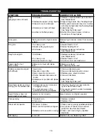
Page 10: ...erload protection tripped 3 Defective or loose switch or wiring Loose belt CORRECTIVE ACTION 1 Reverse or replace blades per instructions See Maintenance 2 Support long boards See Avoiding Snipe 3 Gently push board when board is in contact with only one feed roller See Avoiding Snipe 4 Adjust rollercase See Adjusting Table Level 5 Butt end to end each piece of stock as boards pass through planer R...

Page 11: ...11 NOTES ...

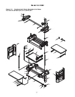
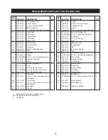
Page 12: ...1 1A 2 3 4 5 7 6 8 8 9 13 24 22 23 21 20 10 32 33 34 35 36 37 38 39 17 18 19 23 25 26 27 31 30 29 28 10 11 14 15 12 16 10 PEFM 5P QVSDIBTF SFQMBDFNFOU QBSUT DBMM ...

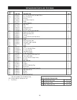
Page 13: ...5 x 19 x 2mm 1 12 30684 00 Elevating Screw LH 1 13 30685 01 Column 4 14 18349 00 6 1 0 x 25mm Socket Head Screw 3 15 30686 00 Guide 2 16 30690 00 Table 1 17 30687 01 Elevating Screw RH 1 18 30688 00 Extension Table Assembly 2 19 30689 00 Table Support 4 20 N A Base 1 21 30691 00 Plate 3 22 01640 00 6 1 0 x 16mm Set Screw 3 23 STD840610 6 1 0mm Hex Nut 4 24 30692 00 Adjustment Screw 4 25 STD852010 ...

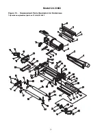
Page 14: ... PEFM 5P QVSDIBTF SFQMBDFNFOU QBSUT DBMM ...

Page 15: ...0708 01 Brush Cap 2 44 30720 00 Gib 2 14 00533 00 3AM1 15 Retaining Ring 3 45 24799 01 16 1 5mm Hex Nut 1 15 18280 00 Chain 2 46 03841 00 Belt 1 16 18337 00 Sprocket 4 47 30721 00 Cutterhead Pulley 1 17 18328 00 Spacer 1 48 STD870512 5 0 8 x 12mm Socket Head Bolt 11 18 STD870535 5 0 8 x 35mm Socket Head Bolt 4 49 24819 00 Motor Pulley 1 19 30709 01 Gearbox Assembly 1 50 18272 00 Bearing Retainer 1...

Page 16: ...utilice siempre una máscara para la cara o respirador ade cuadamente ajustados aprobados por OSHA NIOSH PRECAUCION Aplique siempre los procedimientos de operación correctos tal como se definen en este manual aun cuando esté familiarizado con el uso de ésta u otras herramientas similares Recuerde que descuidarse aunque sólo sea por una fracción de segundo puede ocasionarle graves lesiones PREPARESE...

Page 17: ...e contacto con la cuchilla involuntariamente Conozca su herramienta Aprenda a manejar la herramienta su aplicación y limitaciones específicas Use los accesorios recomendados vea la página 13 Si se usan accesorios incorrectos se puede correr el riesgo de lesionar a las personas Manipule correctamente la pieza de trabajo Protéjase las manos de posibles lesiones Apague la máquina si se atasca La cuch...

Page 18: ...e esté usando la herramienta La base de la cepilladora tiene cuatro agujeros de montaje Monte la cepilladora en el banco de trabajo o en la plataforma de soporteutilizando pernos arandelas planas y tuercas hexagonales no incluidos La Figura 4 muestra las dimensiones de la base los orifi cios de montaje y el espacio necesario para colocar el conjunto de la mesa en posición horizontal Monte firmemen...

Page 19: ...erde o terminal rígido en un lado del adaptador a una toma de tierra permanente p ej una tubería de agua puesta a tierra una caja de tomacorriente puesta a tierra o un sistema de cables puesto a tierra Muchas veces los tornillos de la chapa de cubierta las tuberías de agua y las cajas de tomacorriente no están correctamente puestos a tierra Para garantizar que la conexión a tierra es efectiva un e...

Page 20: ...úrese de comprender todas las precauciones vea las páginas 20 21 24 y 25 Cuando ajuste o reemplace cualquier pieza de la cepilla dora lleve el interruptor a la posición OFF apagado y retire el enchufe de la fuente de alimentación Asegúrese que todos los protectores estén correctamente acoplados y firmemente sujetos Asegúrese que nada obstaculice ninguna pieza móvil Siempre use protección para los ...

Page 21: ...a de rodillos para cortar 3 32 El espesor máximo de la madera que se puede eliminar en una pasada es de 1 32 en piezas de trabajo desde 5 hasta 121 2 de ancho PRECAUCION Se puede efectuar un corte de 3 32 de profun didad en madera dura o blanda de 6 12 de ancho No obstante trabajar continuamente con esta configuración puede hacer fallar el motor prematuramente Si se desea obtener el mejor desempeñ...

Page 22: ... de retorno en la parte superior de modo que el ayudante pueda devolverle la pieza al operador AVISO El ayudante tiene que tomar las mismas precauciones que el operador La superficie que produce la cepilladora es más lisa si se usa una profundidad de corte menor Cómo evitar el redondeo El redondeo se refiere a la depresión en cualquier extremo de la tabla producido por una fuerza dispareja en el p...

Page 23: ...epillo del motor AVISO Los cepillos están situados en las partes delantera y trasera de la cepilladora Reemplace los cepillos si el resorte está dañado Reemplace los cepillos si el carbón está desgastado Reemplace los cepillos y apriete los tapacepillos AJUSTE DEL NIVEL DE LA MESA Vea las Figuras 14 y 15 páginas 12 y 14 La cepilladora producirá una profundidad de corte dispareja corte ahusado si l...

Page 24: ...ga pasar la correa por las poleas de manera inversa a como cuando la extrajo Asegúrese que la correa esté asentada completamente en las ranuras de tanto la polea del motor como de la impulsora Apalanque el motor hacia arriba para aplicar tensión a la correa Asegure en posición apretando el perno Fig 15 Clave No 38 Vuelva a colocar la protección de la correa y los tornillos Fig 15 Claves No 29 y 30...

Page 25: ...abajo larga Indicador no ajustado correctamente 1 Rueda dentada desgastada 2 Cadena desgastada MEDIDAS CORRECTIVAS 1 Invierta o reemplace las cuchillas según las instrucciones Vea Mantenimiento 2 Soporte las tablas largas Vea Cómo evitar el rodamiento 3 Suavemente empuje la tabla cuando esté en ontacto con sólo un rodillo alimentador Vea Cómo evitar el rodamiento 4 Ajuste la caja de rodillos Vea A...

Page 26: ...cableado defectuosos o sueltos Correa suelta MEDIDAS CORRECTIVAS 1 Un electricista calificado debe revisar la fuente de alimentación 2 Apague la cepilladora Reajuste la protección contra la sobrecarga del motor Vea Reajuste de sobrecarga 3 Un electricista calificado debe revisar el interruptor y el cableado Reemplace la correa vea Reemplazo de la correa en V IDENTIFICACION DE PROBLEMAS CONTINUACIO...

Page 27: ...27 NOTAS ...

Page 28: ...stas a preguntas o problemas y ordenar piezas o pedir servicio para la reparación de su equipo To help us help you register your product at www craftsman com registration Para poderte ayudar mejor registra tu producto en www craftsman com registration Join the Craftsman Club today Receive exclusive member benefits including special pricing and offers project sharing expert advice and SHOP YOUR WAY...

Reviews: