background image

Summary of Contents for 107.280070

Page 1: ...N Before using this product read the manual and follow all its Safety Rules and Operating Instructions For answers to your questions about this product call 1 800 659 5917 Sears Craftsman Help Line 5 am 5 pm Mon Sat Sears Brands Management Corporation Hoffman Estates IL 60179 U S A Visit our Craftsman website www craftsman com 7 04938 Revision A ...

Page 2: ...signed andintended onlyforlawn workorsnowremoval andarenotintended foranyotherpurpose Itisimportant thatyoureadandunderstand these instructions thoroughly before attempting to startoroperate thisequipment Savetheseoriginalinstructions for future reference Where to Find Us You never have to look far to find support and service for your CRAFTSMAN mower There are authorized service dealers in North A...

Page 3: ...uel Filter 21 Engine Maintenance 21 Washing the Mower Deck 22 Storage 22 Adjustments and Service 23 Seat Adjustments 23 Ground Speed Lever Adjustment 23 Speed Balancing Adjustment 23 Cutting Height Adjustment 24 Mower Removal and Installation 24 PTO Clutch Adjustment 26 Check Mower Blade Stoppping Time 26 Mower Deck Leveling 27 Servicing the Mower Blades 28 Lubrication 29 Cleaning the Battery and ...

Page 4: ...u have chosen ask a professional contact your local authorized dealer Read the Manual The operator s manual contains important safety infor mation you need to be aware of BEFORE you operate your unit as well as DURING operation Safe operating techniques an explanation of the prod uct s features and controls and maintenance informa tion is included to help you get the most out of your equipment inv...

Page 5: ... throw debris that could seriously injure a bystander Be sure to clean up the area to be mowed and remove objects that could be thrown by the blade BEFORE you start mowing Do not operate this unit without the entire grass catcher or discharge guard deflector in place Also do not allow anyone in the area while the unit is running If some one does enter the area shut the unit off immediately until t...

Page 6: ...e engine is hot or running Allow engine to cool for at least 3 minutes prior to adding fuel Do not add fuel indoors in an enclosed trailer garage or any other enclosed area that is not well ventilated Gasoline spills should be cleaned up promptly and before operation begins Gasoline should be stored only in sealed containers approved for fuel Proper maintenance is critical to the safety and perfor...

Page 7: ...pes exceeding 10 degrees 18 grade 2 Exercise EXTREME CAUTION on all slopes Turn blades OFF when traveling uphill Use a slow speed and avoid sudden or sharp turns 3 DO NOT operate machine back and forth across face of slopes Operate up and down Practice on slopes with blades off 4 AVOID starting stopping or turning on slopes If machine stops going uphill or tires lose traction turn blades OFF and b...

Page 8: ...Never overfill a fuel tank Replace fuel cap and tigh ten securely OPERATION 1 Mount and dismount machine from left side Keep clear of discharge opening at all times 2 Start engine from operator s seat if possible Make sure blades are OFF and parking brake is set 3 DO NOT leave machine with engine running STOP engine STOP blades SET brake and Remove key before leaving operators position of any reas...

Page 9: ...se injury 8 DO NOT work under machine without safety blocks 9 Service engine and make adjustments only when engine is stopped Remove spark plug wire s from spark plug s and secure wire s away from spark plug s 10 DO NOT change engine governor speed settings or overspeed engine 11 Lubricate machine at intervals specified in manual to prevent controls from binding 12 Mower blades are sharp and can c...

Page 10: ...e turns gradually to prevent tipping or loss of control Exercise extreme caution when changing direction on slopes Braking may be affected by attachments Reduce speed on slopes 1 Fold this page along dotted line indicated above 2 Hold page before you so that its left edge is vertically parallel to a tree trunk or other upright structure 3 Sight across the fold in the direction of hill slope you wa...

Page 11: ...children even with the blades df They maylall or return Ior another ride when you are not expecbng d Look down _nd behind before and while backing Roll overhazard Operating on slopes can cause lose of control arid roll overs Avoid sudden turns If you cannot back up a hill do Ilot drive on it r_ _ Go up and down slopes not across If machine stops while going uphill turn the blades off and backdown ...

Page 12: ...D Ground speed levers are locked into their START PARK positions TEST 3 ENGINE SHOULD SHUT OFF IF off seat with PTO engaged OR off seat with parking brake dis Operator rises off seat with ground speed levers not locked in their START PARK positions TEST 4 CHECK MOWER BLADE STOPPING TiME The mower blades and mower drive belt should come to a complete stop within five seconds after the electric PTO ...

Page 13: ...increases the FORWARD speed of the associated wheel and pulling back on a lever increases the REVERSE speed The further a lever is moved away from the neutral posi tion the faster the drive wheel will turn See the Operation section for steering instructions Engine Speed Choke Control Choke O IVlatic The engine speed choke control controls the engine speed and choke Move the engine speed control to...

Page 14: ...sengage Note that the operator must be seated firmly in the rider seat for the PTO to function Transmission Release Levers The transmission release levers deactivate the transmissions so that the unit can be pushed by hand see Pushing the Unit by Hand Seat Adjustment Lever The seat can be adjusted forward and backward see Seat Adjustments Fuel Tank Cap To remove the cap turn counterclockwise Mower...

Page 15: ...ations AWARNING Never allow passengers to ride on the unit Before leaving the operator s position for any reason lock the ground speed levers in the START PARK position engage the parking brake disengage the PTO stop the engine and remove the key To reduce fire hazard keep the engine rider and mower free of grass leaves and excess grease Do not stop or park rider over dry leaves grass or combustib...

Page 16: ...1 Make sure the PTO switch is disengaged the parking brake is engaged the ground speed levers are locked in their START PARK positions and the operator is in the seat 2 Start the engine see Starting the Engine 3 Set the mower cutting height see Cutting Height Adjustment 4 Set the engine speed control to FAST 5 Disengage the parking brake 6 Engage the PTO by pulling up on the switch 7 Pivot the gro...

Page 17: ...ers Smooth Travel The ground speed levers of the zero turn rider are responsive The BEST method of handling the ground speed levers is in three steps as shown in Figure 3 FIRST place your hands onto the levers as shown SECOND to go forward gradually push the levers forward with your palms THIRD to speed up move the levers farther forward To slow down smoothly slowly move the levers toward neu tral...

Page 18: ...o Turn Your zero turn rider s unique ability to turn in place allows you to turn around at the end of a cutting row rather than having to stop and Y turn before starting a new row For example to execute a right end of row zero turn 2 Slow down at the end of the row Move the LEFT ground speed lever forward slightly while moving the RIGHT ground speed lever back to center and then slightly back from...

Page 19: ...uce towed weight when operating on slopes The surface being driven on greatly impacts traction and stability Wet or slippery surfaces can greatly reduce traction and the ability to stop or turn Carefully evaluate the surface conditions before oper ating the unit and trailer and never operate on slopes greater than 10 See Protection Against Tipovers and Towing in the Operator Safety section of this...

Page 20: ...ichever comes first Check blades more often in regions with sandy soils or high dust conditions i i i i i i j i ii i i i i i i i i i i i iiiiiii i i i i iiiiii iiiii iiiiiii iiii iii First 5 Hours Change engine oil Every 8 Hours or Daily Check engine oil level Every 25 Hours or Annually Clean engine air filter and pre cleaner Every 50 Hours or Annually Change engine oil Replace oil filter Replace ...

Page 21: ...uel filter A Figure 11 4 Remove hoses from filter 5 Install new filter in proper flow direction in fuel line 6 Secure with hose clamps 7 Reconnect the negative battery cable when finished Engine Maintenance Refer to engine manual for all engine maintenance pro cedures and recommendations Tire Pressure Front 25 psi 1 72 bar Rear 15 psi 1 03 bar Figure 10 Checking Tire Pressure 4 WARNING Gasoline is...

Page 22: ... in the operator position and there must be no bystanders Failure to follow these precautions may result in serious injury or death Storage Before you store your unit for the off season read the Maintenance and Storage instructions in the Operator Safety section then perform the following steps Disengage the PTO move the ground speed levers into the START PARK positions set the parking brake remov...

Page 23: ...ove the ground speed lever mounting hardware Figure 14 and reposition the lever either up or down from its original position Replace the hardware Figure 14 Ground Speed Lever Adjustments Speed Balancing Adjustment If the rider drifts to the right or left when the ground speed levers are in the maximum forward position the top speed of each of these levers can be balanced Only adjust the speed of t...

Page 24: ...and wait for all moving parts to stop 2 Place a 2 x 4 or similiar support under each end of the mower deck then lower the mower deck to its lowest position See Cutting Height Adjustment 3 Pull back on the tensioning idler F Figure 16 in the direction indicated by the arrow and remove the mower belt from the PTO pulley C Figure 15 Cutting Height Adjustment Figure 16 Mower Belt Routing Remove the ha...

Page 25: ... the front lift rods C Figure 18 into the bottom holes in the front mower deck bracket B and secure each with a washer and hairpin clip A 5 Insert the rear lift arms C Figure 17 into the front holes in the rear mower deck brackets B and secure each with a washer and hairpin clip A 6 Pull back on the tensioning idler D Figure 16 in the direction indicated and install the belt onto the PTO pulley as...

Page 26: ...and removed and make any necessary adjustments by tightening or loosening the adjustment nuts NOTE The actual air gap between the rotor and arma ture may vary even after performing the adjustment pro cedure This is due to dimensional variations on compo nent parts and is an acceptable condition 6 Check the mower blade stopping time The mower blades and mower drive belt should come to a com plete s...

Page 27: ...the right and left rear sides of the mower deck Loosen the jam nuts C and adjust the nuts up or down to adjust the mower level When complete tighten the jam nuts against the trunnion to lock the adjustment in place Front To Back Leveling 6 Arrange the blades so they face front to back Figure 24 7 Measure the distance from the ground to the front tip of the center blade and from the ground to the r...

Page 28: ...h a drop of oil A balanced blade will remain level 6 Reinstall the blade Figure 28 with the tabs pointing up toward the mower deck as shown 7 Reinstall the blade washer B Figure 28 concave side up and bolt C Use a wooden block A to prevent blade rotation while tightening the hardware Torque hardware to 50 60 ft lbs 68 81 Nm WARNING I or your personal safety blade mounting hardware must be installe...

Page 29: ...o moving parts when grease fittings are not installed Not all greases are compatible Use automotive type lithium grease Some blade spindles have grease fittings above the mower deck while others have grease fittings below the deck Oil l ground speed lever pivot points discharge chute hinge deck lift pivot points Generally all moving metal parts should be oiled where contact is made with other part...

Page 30: ...ou need to replace the battery see Cleaning the Battery and Cables section To charge the battery follow the instructions provided by the battery charger manufacturer as well as all warnings included in the safety section of this book Remove the battery from the rider and place on a level non concrete surface Charge the battery at 6 10 amps for 1 hour Do not charge at a rate higher than 10 amps Fig...

Page 31: ...al or incorrectly gapped Water in fuel Drain fuel and refill with fresh fuel Circuit breaker blown See authorized service dealer Fuel mixture too rich Clean air filter Check the choke Engine starts hard or runs Spark plug faulty fouled or Clean and gap or replace See engine manual poorly incorrectly gapped Fuel filter dirty Replace fuel filter Low oil level Check add oil as required Engine knocks ...

Page 32: ...ower cut is rough looking Mower drive belt slipping See authorized service dealer because it is oily or worn Blades not properly fastened See Servicing the Mower Blades to spindles Engine speed too slow Set engine speed control to FAST Ground speed too fast Decrease ground speed Engine stalls easily with Cutting height set too low Cut tall grass at maximum cutting height during first pass i mower ...

Page 33: ...ty of Automotive Engineers code J1940 Small Engine Power Torque Rating Procedure and rating performance has been obtained and corrected in accordance with SAE J1995 Revision 2002 05 Torque values are derived at 3060 RPM horsepow er values are derived at 3600 RPM Actual gross engine power will be lower and is affected by among other things ambient operating conditions and engine to engine variabili...

Page 34: ...dard maintenance servicing oil changes or tune ups Tire replacement or repair caused by punctures from outside objects such as nails thorns stumps or glass Tire or wheel replacement or repair resulting from normal wear accident or improper operation or maintenance Repairs necessary because of operator abuse including but not limited to damage caused by towing objects beyond the capability of the r...

Page 35: ...tion phone support from a Sears representative Think of us as a talking owner s manual Once you purchase the Repair Protection Agreement a simple phone call is all that it takes for you to schedule service You can call anytime day or night or schedule a service appointment online The Repair Protection Agreement is a risk free purchase If you cancel for any reason during the product warranty period...

Page 36: ...36 ...

Page 37: ...PTS I ...

Page 38: ...Frame Assembly ZTS7000 107 280070 NOTE Unless noted otherwise use the standard hardware torque specification chart t PTS 2 ...

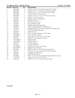
Page 39: ...t Square Neck Carriage GR 5 SCREW 3 8 16 x 3 4 Hex Head Cap GR 5 ZP BRACKET Support Fuel Tank NUT 3 8 16 Hex Flange lock GR F BZ NUT 5 16 18 Hex Flange Lock GR 5 NUT 5 16 18 Nyloc YZ WASHER 34 x 62 x 16 Ga Flat SCREW 5 16 18 x 1 Hex Head Cap GR 5 YZ SCREW 5 16 18 x 3 4 Hex Washer Self Tap YZ NUT 1 2 13 Hex Center Lock GR 5 YZ SPRING Torsion RH Wind WELDMENT Hydro Idler MY08 SPACER Hydro Idler WASH...

Page 40: ...Rear Bumper Assembly ZTS7000 107 280070 NOTE Unless noted otherwise use the standard hardware torque specification chart PTS 4 ...

Page 41: ...654SM 2 7 1927557SM 2 8 1664847SM 4 DESCRIPTION PLATE Brand TUBE Bumper Upper 285Z TUBE Bumper Lower 285Z BOLT 5 16 18 x 1 3 4 Round Head Short Square Neck NUT 5 16 18 Hex Flange Nyloc BOLT Shoulder NUT 5 16 18 Hex Flange Lock Large Black SCREW 5 16 18 x 3 4 Hex Washer Head Self Tap Black ZTS7000 107 280070 Footnotes PTS 5 ...

Page 42: ...Engine Group B S V Twin ZTS7000 107 280070 NOTE Unless noted otherwise use the standard hardware torque specification chart _i _ _ PTS 6 ...

Page 43: ...Ref 8 9 10 CAP Fuel Tank Included with Ref No 7 ASSEMBLY Fuel Hose Included with Ref No 7 BUSHING Fuel Included with Ref No 7 CLAMP Fuel Hose ASSEMBLY Throttle Choke A Matic B S V Twin CABLE TIE 7 HOSE Fuel NUT 5 16 18 Hex GR 5 or B YZ WASHER 5 16 Split Lock WASHER 5 16 Flat NUT 1 4 20 Hex Flange Lock GR 5 YZ SCREW 5 16 18 x 3 4 Hex Flange Lock Black MANIFOLD B S V Twin GASKET Exhaust B S Reg No C...

Page 44: ...Engine Group B S V Twin ZTS7000 107 280070 NOTE Unless noted otherwise use the standard hardware torque specification chart _i _ _ PTS 8 ...

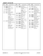
Page 45: ...Engine Group B S V Twin REF NO PART NO QTY 44 445877 0132 B1 1 DESCRIPTION ENGINE 26 HP B S V Twin ZTS7000 107 280070 Footnotes Note Purchase engine parts from engine manufacturer dealer PTS 9 ...

Page 46: ...Front Axle Group RZT26520 ZTS7000 107 280070 NOTE Unless noted otherwise use the standard hardware torque specification chart PTS 10 ...

Page 47: ...Axle PLATE Friction Adhesive Backed BRACKET Axle Support WELDMENT Caster Yoke Spindle Sears Black NUT 5 16 18 Hex Top Lock GR B WASHER 5 16 Flat SCREW 5 16 18 x 3 4 Hex Head Cap GR 5 YZ NUT 5 16 18 Flange Lock YZ NUT 1 2 13 Hex Flange Two Way Lock Black BOLT 5 16 18 x 3 4 Round Head Short Square Neck GR 5 YZ BOLT 5 16 18 x 7 8 Round Head Short Square Neck GR 5 Black BOLT 5 16 18 x 5 8 Hex Flange l...

Page 48: ...Transaxle Group EZT26520 ZTS7000 107 280070 NOTE Unless noted otherwise use the standard hardware torque specification chart 34 Jl _2 PTS 12 ...

Page 49: ...6 I D SCREW 5 16 18 x 3 4 Hex Washer Self Tap YZ BRACKET Transaxle Support SCREW 5 16 18 x 2 3 4 Hex Head Cap GR 5 YZ WASHER 5 16 Flat NUT 5 16 18 Hex Center Lock YZ FENDER WASHER 5 16 RUBBER Anti Rotation SCREW 5 16 18 x 1 3 4 Hex Head Cap GR 5 YZ ROD Roll Release CAP Vinyl CLIP Rod End Clevis LH for 188 Dia Rod CLIP Rod End Clevis RH for 188 Dia Rod NUT 5 16 18 Hex Flange Center Lock KIT FAN PUL...

Page 50: ...Control Group Left Hand ZTS7000 107 280070 NOTE Unless noted otherwise use the standard hardware torque specification chart PTS 14 ...

Page 51: ...d NUT 3 8 24 Hex GR B YZ ROD Link Foward Reverse 3 8 24 thread PIN 7 16 x 1 Clevis WASHER 3 8 Flat COTTER PIN 1 2 Self YZ NUT 3 8 16 Hex Center Lock YZ ROD Handle R H WASHER 64 x 99 x 05 Flat YZ BUSHING WASHER 5 8 ID x 1 00 OD x 065 Nylon NUT 5 8 18 Hex Nyloc YZ WASHER 3 8 Flat SAE SPACER Sleeve RZT SCREW 5 16 18 x 1 1 2 Hex Head Cap YZ DAMPENER Control SCREW 5 16 18 x 2 Hex Head Cap GR 5 YZ SCREW...

Page 52: ...Control Group Right Hand Electric Height of Cut ZTS7000 107 280070 NOTE Unless noted otherwise use the standard hardware torque specification chart 17 PTS 16 ...

Page 53: ... 2 3 4 Hex Head Cap GR 5 YZ SCREW 3 8 16 x 1 Hex Washer Self Tap BRACKET Mount Motor CONTROL BRACKET RH SCREW 1 4 20 x 3 4 Hex Washer Self Tap Black BRACKET Switch SCREW 10 24 x 1 2 Hex Washer Self Tap Torx PLATE Foward Reverse Adjust BRACKET Guide Stick Control RH BOLT 1 4 20 x 5 8 Round Head Short Square Neck GR 5 YZ NUT 1 4 20 Hex Flange Lock Black HANDLE GRIP Handle LOCKWASHER 1 4 Spring YZ SC...

Page 54: ...rt R H Lever 9 To Headlight Switch PTO NOTE Grounding Plunger Grounds Magneto unless fully depressed 11 5 To Startet on engine Brake 22 L HoLever 13 15 21 23 To Circuit Breaker Rear Post To Engine Ground 16 To Electric Clutch _ Ref Jumper _ Harness see Engine Group ine lO pport Bracket see Seat Group Sliding PTS 18 ...

Page 55: ... 19 24 SWITCH PTO Push Pull Symbols COVER Terminal Red Vinyl COVER Battery Cable Red SWITCH Push Button NC SWITCH DPDT NC NO SCREW 1 4 20 x 5 8 Hex Head Cap GR 5 CABLE Starter 8 Gage 14 Black SOLENOID Super Trombetta 2 Terminal SCREW 1 4 20 x 5 8 Hex Head Cap GR 5 or B NUT 1 4 20 Hex Nyloc WASHER 1 4 Flat NUT 1 4 20 Hex Flange Lock YZ HOLD DOWN Battery BRACKET Battery NUT 5 8 32 E Start Included i...

Page 56: ...Seat Group Sliding ZTS7000 107 280070 NOTE Unless noted otherwise use the standard hardware torque specification chart z _2 li 6i PTS 20 ...

Page 57: ...SEAT 15 Back PLATE Seat Adjustable BRACKET Support Seat Fender BRACKET Seat Support BRACKET Seat RETAINER 5 16 Bolt Black LATCH Seat COVER Seat Adjustment Lever SPACER Seat Adjustable FENDER WASHER 5 16 SHOULDER BOLT 5 16 18 x 1 SCREW 3 8 16 x 5 8 Hex Washer Self Tap WASHER 5 16 Flat 341 ID x 1 00 OD x 13 Thick Black SCREW 5 16 18 x 1 1 4 Hex Head Flange Lock SPRING 3 62 Compression BOLT 5 16 18 x...

Page 58: ...Park Brake Group RZT26520 ZTS7000 107 280070 NOTE Unless noted otherwise use the standard hardware torque specification chart i PTS 22 ...

Page 59: ...Lock Black SCREW 3 8 16 x 2 1 4 Hex Head Cap GR 5 YZ BRACKET Lever Park Brake WASHER 3 8 Flat NUT 8 32 Hex GR 2B LEVER Throttle Control SCREW 8 32 x 3 8 Cross Recess Filister Head GR 2 LEVER Brake Park SCREW 10 24 x 1 2 Hex Washer Self Tap Torx SPRING Friction Pack NUT 3 8 16 Hex Nyloc YZ CABLE Park Brake RZT BRACKET Cable Park Brake SCREW 1 4 20 x 5 8 Hex Head Cap GR 5 ROD Park Brake RZT SPRING E...

Page 60: ...52 Deck Lift Group Electric Height of Cut ZTS7000 107 280070 NOTE Unless noted otherwise use the standard hardware torque specification chart PTS 24 ...

Page 61: ... SHOULDER BOLT 1 4 20 x 3 8 WASHER 3 8 Flat SAE HAIR PIN 3 32 x 1 1 2 YZ SCREW 1 4 20 x 5 8 Hex Head Cap GR 5 NUT 1 4 20 Hex Nytoc YZ CLEVIS PIN 25 x 1 09 LEVER Indicator Height Of Cut WASHER 5 16 Nylon BRACKET Indicator Height Of Cut SPRING Compression COTTER PIN 06 x 1 2 YZ WELDMENT Deck Lift 38 42 BEARING Flange 75 ID PM SPACER Bearing 25 SCREW 1 4 20 x 3 4 Hex Head Cap GR 5 YZ SHEAR PIN 248 ID...

Page 62: ...52 Deck Lift Group Electric Height of Cut ZTS7000 107 280070 NOTE Unless noted otherwise use the standard hardware torque specification chart PTS 26 ...

Page 63: ...52 Deck Lift Group Electric Height of Cut REF NO PART NO QTY DESCRIPTION 44 7027168SM 2 CAPSCREW Hex Head 5 16 18 x 1 45 7091593SM 2 COTTER PIN 3 8 Self Lock ZTS7000 107 280070 Footnotes PTS 27 ...

Page 64: ...Wheel Tire Group ZTS7000 107 280070 NOTE Unless noted otherwise use the standard hardware torque specification chart PTS 28 ...

Page 65: ...eel Rim Incl Ref 1C AIR VALVE STEM Snap In Included with Ref 1 LUG NUT 1 2 20 Tapered Seat YZ ASSEMBLY Wheel Tire Sears ZTS 11 x 4 5 Incl Ref 3C 3D 3E GREASE FITTING 8M x 1 threads 45 degree included with Ref 3 VALVE Air Included with Ref 3 BUSHING 0 6321D 1 377OD 62 Included with Ref 3 NUT 7 16 14 Hex Center Lock GR 5 or B SCREW 7 16 14NC x 6 Flex Head Cap GR 5 YZ TUBE Caster Wheel 0 625 OD 4 53 ...

Page 66: ...Deca s ZTS7000 107 280070 NOTE Unless noted otherwise use the standard hardware torque specification chart PTS 30 ...

Page 67: ... DECAL DECAL DECAL DECAL DECAL DECAL DECAL DECAL DECAL DECAL DECAL DECAL DECAL DECAL Rear Craftsman ZTS Instructional 285Z Handle Ground Speed RH 285Z Safety Symbol 285Z Control Panel RH 285Z DANGER English 285Z Release Transaxle 285Z Caution Screen Rotating 52 Deck Model Craftsman ZTS Weight Limitation Warning Burn Hazard LH Fender Craftsman ZTS RH Fender Craftsman ZTS Control Panel LH 285Z WARNI...

Page 68: ...Fender Group ZTS7000 107 280070 NOTE Unless noted otherwise use the standard hardware torque specification chart tO 2 _4 PTS 32 ...

Page 69: ... 13 7301126BMYP 14 7027168SM 15 7091503SM QTY 1 1 1 1 1 2 1 2 2 4 2 2 1 2 1 DESCRIPTION FENDER LH FENDER RH COVER Engine ROD Pivot Hood COVER BATTERY 285z NUT Hex Flange ESNA 3 8 16 PLUG Hole STRIP TRIM SCREW 1 4 20 x 3 4 Pan Head Self Tap Torx U NUT 1 4 20 BRACKET Support Fender NUT 5 16 18 3B Nyloc YZ PLATE Side RH SCREW 5 16 18 x 1 Hex Head Cap GR 5 YZ HAIR PIN 3 32 x 1 1 2 YZ Footnotes PTS 33 ...

Page 70: ... 13 4 03 03 4_ 4 4 4 ...

Page 71: ...Wiring Schematic REF NO PART NO 1 7103412YP QTY 1 DESCRIPTION HARNESS Wiring ZTS7000 107 280070 Footnotes PTS 35 ...

Page 72: ...52 Mower Deck Housing Group ZTS7000 107 280070 NOTE Unless noted otherwise use the standard hardware torque specification chart i PTS 36 ...

Page 73: ...IPTION HOUSING 52 Mower NUT Hex Flange Whiz Lock 5 16 18 BRACKET L H Rear BRACKET R H Rear BOLT 5 16 18 x 7 8 Round Head Short Square Neck GR 5 Black NUT 5 16 18 Hex Flange Lock Small Black SUPPORT Rear Cross SCREW 5 16 18 x 1 Hex Washer Head Self Tap Black NUT 5 16 18 Hex Flange Nyloc BRACKET Gauge Wheel LH BRACKET Gauge Wheel RH HITCH Front SHOULDER BOLT 3 8 16 x 3 41 750 Thread Yellow WASHER 1 ...

Page 74: ...52 Mower Deck idler Group ZTS7000 107 280070 NOTE Unless noted otherwise use the standard hardware torque specification chart PTS 38 ...

Page 75: ... Black NUT 5 16 18 Hex Flange Lock Large Black SCREW 3 8 16 x 2 1 2 Hex Head Cap GR 5 Black WASHER 3 8 Flat 41 ID x 87 OD PULLEY Idler 46 52 Mowers BRACKET Idler Rear RZT NUT 3 8 16 Hex Flange lock GR F BZ ARM Idler 46 52 RZT WASHER 406 x 1 50 x 120 Flat Yellow Zinc SPACER 406 ID x 1 50 OD x 350 Thick PM SPRING Extension PTO NUT 3 8 16 Hex Flange Lock Large Black BRACKET Idler Mount Front Black SC...

Page 76: ...52 Mower Deck Spindle Group ZTS7000 107 280070 NOTE Unless noted otherwise use the standard hardware torque specification chart t4 PTS 40 ...

Page 77: ...k LOCKWASHER 438 Spring Black WASHER 475 ID x 1 75 OD x 156 Thick Spring Black PULLEY 5 50D 11 Ga Split SPACER Pulley Powdered Metal RING Self Locking SHIELD Arbor 2 050 OD BALL BEARING 20 MM SPACER Bearing Powdered Metal SHAFT Spindle 20MM Dia 134 60 MM Long HOUSING Spindle Cast Aluminum Machined w Grease Fitting DEFLECTOR Discharge Plastic PUSH NUT 5 16 NUT 5 16 18 Hex Flange Lock Small Black PL...

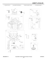
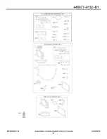
Page 78: ...LACMENT ENGINE 1330 REPAIR MANUAL 85O 10 11_ 252 3 718 _ _ _ 562 212 J278 _ _ 505 _ _ i i i i _ i_ 524 15 s 552 _ _ 552A 742 _ 404 _ _ _ r _ I _ _ L _ _b_ 1013 _ W q 20 75O m A 1027 220 _ 46 45 h MCSOOOOO1 B Assemblies include all parts shown in frames 42 12 02 2010 ...

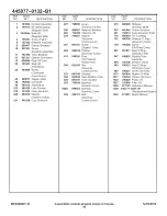
Page 79: ...e 404 690442 Washer Governor Crank 415 690283 Plug Oil Pressure Switch Hole 505 691029 Nut Governor Control Lever 523 691036 Dipstick 524 691032 Seat Dipstick Tube 525 691037 Tube Dipstick 552 796638 Bushing REF PART DESCRIPTION 552A 690553 562 690311 Governor Crank Bushing Governor Crank Bolt Governor Control Lever NO NO 615 698290 Retainer Governor Shaft 616 691045 Crank Governor 691 790574 Seat...

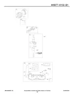
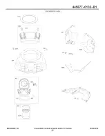
Page 80: ...445877 0132 B1 25i 146 741 _ _ _ _NNN 24 163 929 Q1 54_ 186 L_g _ MCSOOOOO1 B Assemblies include all parts shown in frames 44 12 02 2010 ...

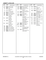
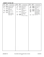
Page 81: ... 27 690975 Lock Piston Pin 28 696581 Pin Piston 29 796209 Rod Connecting 32 690976 Screw Connecting Rod 50 695241 Manifold intake 51 795123 Gasket Intake 51A 690950 Gasket Intake 54 699816 Screw Intake Manifold 146 690979 Key Timing 163 691001 Gasket Air Cleaner 186 795985 Connector Hose Intake Manifold 741 690980 929 695239 Link Throttle Plug Oil Pressure Switch Hole Seat O Ring Intake Manifold R...

Page 82: ...445877 0132 B1 1022 1029 1100 _ 79_j _ 883 34 _ 868 _ 45 1026 _ _ _ _ 1026A _ 918 914 _ _ 918A 13 85O 7 883 1022 1029 635 85O 914_ MCSOOOOO1 B Assemblies include all parts shown in frames 46 12 02 2010 ...

Page 83: ...over Rocker Cylinder 1 7 13 793988 Screw Cylinder Head 33 793557 Valve Exhaust 34 793556 Valve Intake 35 694865 Spring Valve Intake 36 694865 Spring Valve Exhaust 42 499586 Keeper Valve 45 690977 Tappet Valve 635 66538s Boot Spark Plug 798 697890 Screw Rocker Arm 850 100106 Sealant Liquid 868 690968 Seal Valve 883 690970 Gasket Exhaust 914 691127 Screw Rocker Cover 1023A 1026 1026A 1029 1100 49960...

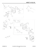
Page 84: ... 0132 B1 654 53 163 1169 108 _ i_ 633 51A I05_ 1126 _ t _j 1124A _ l 104 9751 f __ 137 _ _ 131_95e 130 788 628 _ o _ _ _j 387 385 24O 187 MCSOOOOO1 B Assemblies include all parts shown in frames 48 12 02 2010 ...

Page 85: ...e 163 691001 Gasket Air Cleaner 187 791766 Line Fuel Cut to Required Length 217 695409 Spring Choke Return 231 690718 Screw Choke Valve 240 695666 Filter Fuel 947 798779 975 798778 276 695410 Washer Sealing 385 797409 Screw Fuel Pump Used After Code Date 09081100 Note 697551 Screw Fuel Pump Used Before Code Date 09081200 387 808656 Pump Fuel 418 795912 Plate Carburetor 601A 691038 Clamp Hose Black...

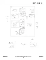
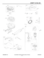
Page 86: ...1036 EMISSIONS LABEL 445877 0132 B1 i968 i 467 J _ 306 305A 3O4 307 307A 306A 865A 431 163 964 573 967B MCSOOOOO1 B Assemblies include all parts shown in frames 50 12 02 2010 ...

Page 87: ...d Cylinder Cylinder 2 Shield Cylinder Cylinder 1 Screw Cylinder Shield 1 4 20x 66 Screw Cylinder Shield 10 24x 437 Elbow Intake Filter Air Cleaner Cartridge REF PART NO NO DESCRIPTION 467 790697 Knob Air Cleaner 573 790444 Plate Back 865A 792286 Cover Air Guide Valley 964 799158 Cap Connector 967B 792303 Filter Pre Cleaner 968 795120 Cover Air Cleaner 1036 Label Emissions Available from a Briggs S...

Page 88: ...l 747 1005 668 668A 1070 332 _ 75 S 23 789 789B 789A 877 ___ _ _ 729 1054 334 851 _ 1119 1012 18_ 209 _ _ _ X 211 801 310 I1 o9ol i 802 b C O_ U_ MCSOOOOO1 B Assemblies include all parts shown in frames 52 12 02 2010 ...

Page 89: ...280275 1059 698516 1070 791680 796226 Bracket Control Used Before Code Date 10072300 265 691024 Clamp Casing 267 691044 Screw Casing Clamp 309 795121 Motor Starter 310 691263 Screw Starter Motor 332 691059 Nut Flywheel 333 691060 Armature Magneto 334 691061 Screw Magneto Armature 474 696458 Alternator 501 797375 Regulator 510 696541 Drive Starter 526 697551 Screw Regulator 635 66538s Boot Spark Pl...

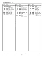
Page 90: ...217_ 276A _ 150 1123 _ P 1124 _J_3 633 633A _ 1124A _ 987 1353 _ p 358 ENGINE GASKET SET 51A 51A _o _ o _ oJ 12 524 _ 691 F_z5 842 xi J 2O 883 1022 868 _ _ 85O 1095 VALVE GASKET SET 51B 883 1022 MCSOOOOO1 B Assemblies include all parts shown in frames 54 12 02 2010 ...

Page 91: ... 691001 Gasket Air Cleaner 276A 794271 Washer Seating 276 695410 Washer Seating 358 694012 Gasket Set Engine 524 691032 Seal Dipstick Tube 633 699813 Seal Choke Throttle Shaft Choke Shaft 633A 699813 Seat Choke Throttle Shaft REF PART DESCRIPTION NO NO 672 690234 691 790574 842 691031 850 100106 868 690968 883 690970 987 691000 1022 690971 1095 694013 1124A 841653 Gasket Carburetor Plate Seat Gove...

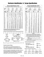
Page 92: ...diameter the second number 16 represents the threads per inch 1 25 thread diameter The final number is the body length of the bolt or screw 2 inches 50ram Torque Specification Chart FORSTANDARD MACHINE HARDWARE Tolerance 20 0 SAE Grads 2 8AEGrads 5 8AEGrads 8 SizeOf in Ibs in Ibs in Ibs Hardware fl ibs Nm fl ibs Nm fifths Nm 8 32 8 36 10 24 10 32 1 4 20 1 4 28 5 16 18 5 16 24 3 8 16 3 8 24 7 16 14...

Page 93: ...arry in items like vacuums lawn equipment and electronics call anytime for the location of your nearest Sears Parts Repair Service Center 1 800 488 1222 U S A 1 800 469 4663 Canada www sears com www sears ca To purchase a protection agreement on a product serviced by Sears 1 800 827 6655 U S A 1 800 361 6665 Canada Para pedir servicio de reparaci6n a domicilio y para ordenar piezas 1 888 SU HOGAR ...

Reviews: