background image

6

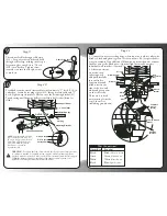
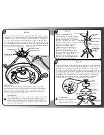
WARNING:

To reduce the risk of fire, electric shock or personal injury, mount to outlet box
marked "acceptable for fan support" and use mounting screws provided with
the outlet box. Most outlet boxes commonly used for the support of lighting
fixtures are not acceptable for fan support and may need to be replaced.
Consult a qualified electrician if in doubt.

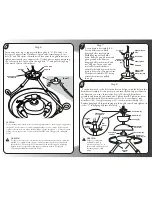
8

WARNING:

Failure to completely
tighten downrod as
described in steps 7 & 8
above could result in the fan
loosening and possibly
falling.

Ground

Wire

Hex Nut

C

A

B

Hex Nut

Down Rod

Inset 1

Ball
Screw

Hanging

Pin

Hanging

Ball

Threaded Set

Screw Hole

Support Arm

Distributor

Safety Bolt

and Nut

Support

Arms

Set Screw (A)

Canopy (3)

Distributor
Assembly (2)

Set Screw (C)

Downrod (2)

Distributor
Cover (8a)

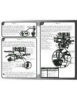
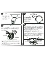
Step 6

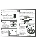
Insert wires from top of support rod through hole "A" (See Inset 1) in
bottom of Support Arm Distributor. Insert end of remaining rod into
hole "B" and in bottom of distributor. Place wires through hex nuts and
tighten nut securely onto support rods. Use hex nuts to secure remaining
two rods into place. Insert wires through hole "C" and pull through top
of downrod section of distributor.

Step 8

Position downrod so the hole in the downrod aligns with the hole in the

distributor assembly. At this point you can turn the Fan Support Arms in
the direction you want. Insert safety bolt (S10) through distributor
assembly and downrod and attach nut. Tighten firmly. Tighten set screw
"A" against downrod. Place distributor cover (#8a) over support arm
distributor (#8). Next place canopy (#3) over downrod assembly (#2).
Replace hanging ball, insert hanging pin through downrod and tighten set
screw "C" in hanging ball into downrod.

Step 7

Locate downrod assembly (#2).

Loosen ball screw on black
hanging ball to free lock pin.
Black hanging ball will slide
down. Remove ground screw and
green ground wire. Remove
hanging ball from downrod and
save all parts. Insert wires and
steel cable from distributor
assembly through downrod. Screw
downrod into top of Support Arm
Distributor Assembly (#8), being
careful that wires are pulled
through.

Hanging Ball

Lock Pin

Support Arm
Distributor
Assembly (#8)

Downrod

Ball Screw

Green Ground
Wire

Downrod

Assembly

(#2)

7

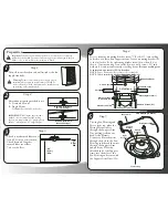
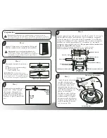
CAUTION:

Do not mount fan to sheet rock or drywall type materials. To insure proper support use
the two #1 wood screws to secure mounting bracket to joist or beam, if the location
you have chosen does not have a suitable support beam, install a 2" x 4" brace between
ceiling joists to support fan, or one of the many NEC and UL approved ceiling fan
braces.

Summary of Contents for Chalice CL52

Page 1: ... www craftmade com MEJOR DISEÑO UNE CONCEPTION EXCEPTIONNELLE P O Box 1037 650 S Royal Lane Suite 100 Coppell TX 75019 EE UU de 8 heures à 17 heures Heure standard du centre Numéro de télécopieur gratuit 877 304 1728 Email customerservice craftmade com www craftmade com P O Box 1037 650 S Royal Lane Suite 100 Coppell TX 75019 800 486 4892 8 00 to 5 00 CST Central Standard Time Toll Free Fax 877 30...

Page 2: ...to grounded conductor of power supply conductor of a fan identified as ungrounded conductor to be connected to an ungrounded conductor of power supply conductor of fan identified for equipment grounding to be connected to an equipment grounding conductor 6 Fan should not be mounted in an area where it might get wet 7 To reduce the risk of fire electric shock or personal injury mount to outlet box ...

Page 3: ...2 1m Min 30 0 75m Min Preparation Important When using an existing outlet box be sure the box is securely attached to the building structure and can support the full weight of the fan Failure to do so can result in serious injury or death Step 2 Determine mounting method to use A Downrod Mount B Angle Mount Craftmade Part 45AD see dealer 2 IMPORTANT If using the angle mount method check to make su...

Page 4: ...od so the hole in the downrod aligns with the hole in the distributor assembly At this point you can turn the Fan Support Arms in the direction you want Insert safety bolt S10 through distributor assembly and downrod and attach nut Tighten firmly Tighten set screw A against downrod Place distributor cover 8a over support arm distributor 8 Next place canopy 3 over downrod assembly 2 Replace hanging...

Page 5: ...ctrician if in doubt Step 11 1 Connect fan wires to ceiling wires white fan wire to white outlet wire black to black and green to green Wire connectors S6 are provided for your convenience If an additional blue wire is present then also connect the blue wire to the black wire Optional light kit may be wired to individual wall switches if desired 2 After connections are made turn splices upward and...

Page 6: ...ched between switch housing and mounting plate Remove rubber cushions saving motor screws for blade installation Using motor screws S5 provided line up holes from the blade arm with the holes in the motor housing Tighten screws securely 12 Step 12 Attach canopy 3 to the mounting bracket by placing screws S2 into slot in canopy Twist clockwise to lock into place Tighten screws firmly Bottom of Cano...

Page 7: ...er all thread from light kit into the center hub cover Lock the all thread in place on the inside of the hub using the 3 8 nut provided For both light kits attach white wire from light kit to white wire in hub using wire nuts Next attach black wire from light kit to blue wire in switch hub Carefully push wires up into hub Reinstall wire harness and secure light kit to fan by replacing the four sid...

Page 8: ...ors provided with your fan No loose strands or loose connections should be present After wires have been connected they must be spread apart so the green and white are on one side of the outlet box and the black and blue are on the other side Turn splices upward and carefully push all wiring into outlet box For optional wall control see figure B or Figure C for alternate wiring When wall switches ...

Page 9: ... installed properly 3 Check to make sure light kit and glass reinstalled properly and tight 4 If wall control is used insure the wall control is not a transformer or a variable speed type Problem C Fan Wobbles Remedies 1 Check that all blades are screwed firmly into blade holders 2 Check that all blade holders are screwed firmly into motor 3 Check the weight of blades All our blades are weighed on...

Page 10: ...de un ventilador identificado como conductor sin tierra debe conectarse a un conductor sin tierra del suministro de alimentación el conductor de un ventilador identificado para conectar a tierra el equipo debe conectarse a un conductor para tal efecto 6 No debe montarse el ventilador en un área donde pueda mojarse 7 Para aminorar el riesgo de un incendio choque eléctrico o lesión personal móntelo ...

Page 11: ...aja de salida existente revise que la caja esté conectada firmemente a la estructura de la edificación y que pueda soportar el peso total del ventilador De lo contrario puede ocasionar lesiones graves o fatales Paso 3 Revise que las aspas queden por lo menos a 30 76 cm de toda obstrucción Compruebe la longitud de la vara hacia abajo para que las aspas queden por lo menos a 7 pies 2 metros del piso...

Page 12: ...ribuidor 8a Paso 8 Ponga la vara hacia abajo de tal modo que el agujero de la vara hacia abajo se alinee con el agujero del ensamblaje del distribuidor Inserte el perno de seguridad S10 a través del ensamblaje del distribuidor y la vara hacia abajo e instale la tuerca Apriete firmemente Apriete el tornillo de fijación A contra la vara hacia abajo Ponga la cubierta del distribuidor 8a sobre el dist...

Page 13: ...cientemente grande para unirlo al gancho J S10 en la caja de salida Apriete el tornillo fuertemente para asegurarse de que el bucle no se suelte Abrazadera para el cable S13 6 10 Paso 10 Para mayor seguridad instale un lazo de alambre de acero desde el ventilador al gancho J S10 en la caja de salida Sujételo pasando la amarra S11 por el cable de seguridad y el gancho J Apriete bien la amarra Levan...

Page 14: ...la hoyos del brazo de hoja con los hoyos en el motor que alberga Apriete los tornillos firmemente Enchufe modular de cableado A Enchufe modular de cableado B Caja del interruptor Tornillos F Ranuras de montaje Placa de montaje E 12 Paso 12 Instale la cúpula 3 en el soporte de montaje colocando los tornillos S2 en la ranura de la cúpula Gire en el sentido de las manecillas del reloj para bloquearla...

Page 15: ...ral en su posición en el interior del cubo con la tuerca de 3 8 incluida Para ambos juegos ligeros una el cable blanco del juego de iluminación al cable blanco situado en el cubo empleando las tuercas para cables Luego una el cable negro del juego de iluminación al cable azul situado en el cubo del interruptor Con cuidado empuje los cables hacia arriba introduciéndolos al cubo Vuelva a instalar ar...

Page 16: ...entilador No debe haber hebras ni conexiones sueltas Después de conectar los cables deben separarse de tal modo que el verde y el blanco queden en un lado de la caja de salida y el negro y el azul queden en el otro lado Gire los empalmes hacia arriba y empuje con cuidado todo el cableado dentro de la caja de salida Para el control opcional de pared consulte la figura B o la figura C para ver cable...

Page 17: ...que el soporte de montaje esté instalado correctamente 3 Compruebe que la unidad de luz y el vidrio estén correctamente instalados y apretados 4 Si se usa el control de pared revise que no sea del tipo transformador o de velocidad variable Problema C El ventilador se balancea Soluciones 1 Revise que todas las aspas estén atornilladas firmemente en sus soportes 2 Revise que todos los soportes de la...

Page 18: ...it être branché sur le conducteur non mis à la masse de l alimentation électrique Le conducteur du ventilateur destiné à la mise à la masse de l équipement doit être connecté à un conducteur de mise à la masse de l équipement 6 Le ventilateur ne peut être installé dans un endroit où il pourrait être mouillé 7 Pour éviter les incendies les décharges électriques ou les blessures branchez le ventilat...

Page 19: ... une tige de suspension Montage à l aide d une tige de suspension 4 OUTLET BOX Boîte de sortie A Supports de montage 1 Vis et rondelles des supports S3 Poutre de soutien Vis à bois S1 Vis de coupelle S2 Plafond Vis à bois S1 Crochet en J S11 5 Étape 5 Boîtier du ventilateur et du moteur Étape 4 Avant de fixer le support de montage vissez le crochet en J S11 sur la boîte de sortie du plafond pour q...

Page 20: ...Écrou hexagonal Écrou hexagonal C A B Tige de suspension Encart 1 Boîte de dérivation du bras de support ATTENTION Ne montez pas le ventilateur sur du placoplâtre ou des matériaux de type pour mur sec Pour assurer un parfait support utilisez les deux vis à bois nº 1 pour installer le support de montage sur une poutrelle ou sur une poutre Si l endroit que vous avez choisi ne comporte pas de poutre ...

Page 21: ...u crochet en J S10 de la boîte de sortie Serrez bien la vis pour être sûr que la boucle ne se desserrera pas Cable Clasp S13 10 Étape 10 Pour plus de sécurité attachez le câble de sécurité du ventilateur au crochet en J S10 accroché dans la boîte de sortie Fixez l installation en faisant passer la bride S11 dans le câble de sécurité et dans le crochet en J Resserrez fortement la bride Installez le...

Page 22: ... d interrupteur S9 Soulevez le couvercle de boîtier d interrupteur n 9 et alignez les trous de montage avec les trous de la plaque de montage E Une fois que les trous sont alignés fixez le couvercle de boîtier d interrupteur au moyen des vis de boîtier d interrupteur S9 et serrez les fermement IMPORTANT vérifiez qu aucun fil n a été coincé ou pincé durant le montage 13 Étape 13 Pour monter les pal...

Page 23: ...nterrupteur DLK 36 retirez tout d abord l assemblage du boîtier de l interrupteur en dévissant les quatre vis latérales et en déconnectant le harnais de câblage Retirez les trois vis situées à l intérieur du boîtier et retenant la plaque centrale en place Retirez la plaque centrale et remplacez la par le kit d éclairage DLK 36 Remettez les trois vis en place Pour installer un kit d éclairage centr...

Page 24: ...Noir Blanc Bleu Vert Blanc Vert Éclairage en option Figure A Problèmes fréquents Problème A Le ventilateur ne démarre pas Solution 1 Vérifiez les fusibles ou le disjoncteur et remplacez les si besoin est 2 Coupez l alimentation électrique et vérifiez tous les connecteurs 3 Vérifiez les interrupteurs on off ainsi que l interrupteur de commande mural Consultez le mode d emploi Problème B Le ventilat...

Reviews: