background image


15

COMPOUND SLIDE 


The compound slide rotates at a set angle 
and features a graduation scale of 0.001". 
 

TO ADJUST THE COMPOUND SLIDE: 

 
Loosen the bolts located on the compound 
slide shown in figure-13. 


Figure-13 Loosening the bolts 


Rotate the compound slide to the desired 
angle. 
 
Tighten the bolt, loosened in the first step 
and make sure the compound slide does 
not move during tightening. 
 
Move the compound slide back and forth 
using the hand wheel and make sure the 
threads are engaging and there is no 
backlash, before you set the hand wheel 
scale to "0". 


CARRIAGE 


The carriage allows the cutting tool to move 
along the length of the lathe bed and the 
carriage movement can be controlled 
manually or automatically. 
 

MANUAL MOVEMENT 


The manual movement of the carriage can 
be controlled using the hand wheel shown 
in figure-14. 


Figure-14 Carriage hand wheel 


Rotating the hand wheel clockwise will 
move the carriage to the right and counter-
clockwise will move the carriage to the left 
on the lathe bed. 


AUTOMATIC MOVEMENT 


To use the autamatic carriage movement, 
set the carriage to the desired starting point 
using the carriage hand wheel. 
 
Turn the variable speed control dial to the 
required RPM. 
 
Move the automatic feed lever down to 
engage the half-nut and activate the 
automatic feed feature. See figure-15. 
 
To deactivate the automatic feed feature, 
simply lift the the automatic feel lever up. 
 
Automatic feed feature also works when 
operating the lathe in reverse direction by 
changing the leadscrew after tunring the 
lathe OFF. 

Summary of Contents for CX704

Page 1: ...CX704 7 x 12 MINI METAL LATHE User Manual ...

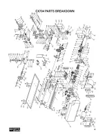
Page 2: ...Jaws Replacement 11 Installing Removing Chuck or Faceplate 11 Tailstock 12 Tailstock Positioning 12 Dead Center 13 Tool Post 13 Steady Rest 13 Cross Slide 14 Compound Slide 15 Carriage 15 Changing Gears 16 Threads Cutting 17 Maintenance 17 Cleaning 17 Lubrication 18 Gibs Adjustment 18 Motor Brushes Replacement 19 Headstock Tailstock Alignment 19 Wiring Diagram 21 Parts Breakdown 22 Parts List 23 W...

Page 3: ...s that may affect your ability or judgment to safely operate your machine DISCONNECT the power source when changing drill bits hollow chisels router bits shaper heads blades knives or making other adjustments or repairs NEVER leave a tool unattended while it is in operation NEVER reach over the machine when the tool is in operation ALWAYS keep blades knives and bits sharpened and properly aligned ...

Page 4: ...r alignment of moving parts broken parts and any other conditions that may effect the tools operation Remove adjusting keys and wrenches Remove all the tools used for adjustment before turning the machine on Be careful Do not put your hand close to the cutter while the machine is running Never leave the lathe unattended while it is running Do not over reach Keep proper footing and balance at all t...

Page 5: ...le Phase 3 Amps Number Of Speeds Variable Swing Over Bed 7 Swing Over Cross Slide RD 2 1 8 Swing Over Saddle 5 Compound Slide Travel 2 3 4 Carriage Travel 10 1 2 Cross Slide Travel 2 3 4 Maximum Tool Bit Size 5 16 Headstock Construction Cast Iron Spindle Bore 20mm Spindle Size 3 Spindle Taper MT 3 Range of Spindle Speeds Low 0 1100 High 0 2500 RPM Tailstock Travel 2 1 2 Tailstock Taper MT 2 No of ...

Page 6: ...tch C Emergency Stop Button D Chuck E Tool Post F Compound Slide G Compound Slide Hand Wheel H Tailstock Quill I Tailstock Quill Lock J Tailstock K Tailstock Hand Wheel L Bed Way M Lead Screw N Thread Dial O Automatic Feed Lever P Cross Slide Hand Wheel Q Carriage Hand Wheel R Gears Cover ...

Page 7: ...ed most of the time UNPACKING To ensure safe transportation this machine is properly packaged and shipped completely in crates When unpacking carefully inspect the crates and ensure that nothing has been damaged during transit Open the crates and check that the machine and the parts are in good condition If you can not find any part check if the part is already installed on the machine Some of the...

Page 8: ... prong grounded receptacle as shown in figure 1 Do not remove the grounding prong to fit it into a 2 pronged outlet Figure 1 110 Volts outlet for CX704 It is strongly recommended not to use extension cords with your CX704 Always try to position your machine close to the power source so that you do not need to use extension cords In case if you really find it necessary to use an extension cord make...

Page 9: ...te direction for shipping purposes Remove the cap srew using a hex wrench and turn the handle around Secure the handle by retightening the cap screw See figure 4 Figure 4 Installing the cross feed hand wheel handle BASIC CONTROLS This section describes the basic controls of the CX704 Use the figure and read the descriptions to understand the basic controls of this lathe Figure 5 Control panel A FU...

Page 10: ...round the machine ensure all nuts bolts and screws are tightened and the machine is properly assembled Locate the High Low range control lever at the back of the lathe and set it to Low range Set the Forward Reverse button to Forward position Connect the cord to the power source and lift the Emergency Stop button Rotate the Variable Speed Control Knob slowly and you will hear a click as the power ...

Page 11: ...ed as A B C or 1 2 3 and the numbers are in the slot on the chuck Insert the jaw in to the slot 1 and turn the chuck key clockwise untill the jaw is engaged with the thread Repeat the same step with jaw 2 and then jaw 3 Make sure the jaws are installed in sequence INSTALLING REMOVING CHUCK OR FACEPLATE The chuck is mounted directly to the spindle nose plate using studs and hex nuts TO REMOVE THE C...

Page 12: ...The offset screw on the tailstock helps maintain tailstock position during tailstock offset adjustment See figure 8 Figure 8 Tailstock controls TAILSTOCK POSITIONING TO ADJUST THE LONGITUDINALLY Make sure the cord is disconnected from the power source Loosen the tailstock lock nut securing the tailstock on the lathe bed with a proper size wrench See figure 9 Figure 9 Loosening the tailstock lock n...

Page 13: ...d with CX704 which rotates to four 90 preset stops or at any angle in between Cutting tools can be attached and removed by tightening or loosening the cap screws on the tool post TO USE THE TOOL POST Attach the cutting tool you want to use to the tool post and secure it by tightening cap screws See figure 10 Figure 10 Proper tool post setup The tip of the cutting tool should be right at the center...

Page 14: ...IDE Move the cross slide back and forth a few turns using the hand wheel and then move it to your starting point This will clear any free movements in the leadscrew increasing accuracy on cross slide scale Hold the hand wheel with one hand and turn the scale so that the 0 mark on the scale lines up with the 0 000 mark on the cross slide See figure 12 Figure 12 Adjusting the cross slide When making...

Page 15: ...ement can be controlled manually or automatically MANUAL MOVEMENT The manual movement of the carriage can be controlled using the hand wheel shown in figure 14 Figure 14 Carriage hand wheel Rotating the hand wheel clockwise will move the carriage to the right and counter clockwise will move the carriage to the left on the lathe bed AUTOMATIC MOVEMENT To use the autamatic carriage movement set the ...

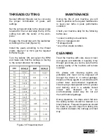
Page 16: ...ve the gear cover to access the gears Loosen the adjusted to disengage the gears from each other Remove the gears and install the new gears according to the chart See figure 17 18 Reinstall the adjuster and close the close the cover Figure 17 Threads per inch chart Figure 18 Metric thread chart WARNING DO NOT change the direction of rotation of leadscrew while the lathe is running Failure to do so...

Page 17: ...our machine daily for the following before use Loose mounting nuts and bolts Worn or damaged cord Damaged parts Any other unsafe condition CLEANING Treat the machine with care keep it clean and grease and lubricate it regularly Only through good care you can be sure that the working quality of the machine will remain constant Oil grease and cleaning agents are pollutants and must not be disposed o...

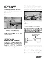
Page 18: ...ar To lubricate the transmission gears disconnect the cord from the power source and remove the front control panel remove the ground wire from the headstock and spray grease in the hole Rotate the chuck with your hand and shift the gears high to low GIBS ADJUSTMENT The cross slide and the compound slide gibs will need to be adjusted after sometimes TO ADJUST THE CROSS SLIDE AND COMPOUND SLIDE GIB...

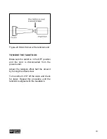
Page 19: ... the headstock and tailstock may be out of alignment TO CHECK THE CENTERS ALIGNMENT Center drill a 6 piece of bar stock on one end and position it between the headstock and tailstock as shown in figure 22 Figure 22 checking headstock and tailstock alignment Turn approximately 0 010 off diameter Measure the stock with a micrometer If the stock is thicker at the tailstock end the tailstock needs to ...

Page 20: ...the switch is in the OFF position and the cord is disconnected from the power outlet Adjust the tailstock offset half the amount by turning the offset screw Turn another 0 010 off the stock and check for taper Repeat this procedure until the tailstock is aligned with the headstock ...

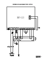
Page 21: ...21 WIRING DIAGRAM FOR CX704 ...

Page 22: ...22 ...

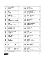
Page 23: ...taining Ring M10 1 29 Timing Belt 1 30 Shifting Fork 1 31 Shifting Arm 1 32 Shifting Knob 1 33 Shifting Lever 1 34 Shifting Grip 1 35 Handle 1 36 Fanning strip 1 37 Compressive Spring 1 38 Indicator 1 39 Pinion 25T 1 40 Support Screw 2 41 Pinion 20T 1 42 Fixed Cover 1 43 Screw M6 20 5 45 Gear 45T 1 46 Shaft 1 47 Parallel Key 1 48 Gear shelf 1 49 Screw M5 18 2 50 Pinion 20T 2 51 Washer 2 52 Screw M...

Page 24: ... M4 8 99 Screw M4 16 3 100 Cross Slide 1 101 Screw M5 10 5 102 Screw M4 8 2 105 Positioning plate 1 106 Screw M4 14 3 107 Gib Strip 1 108 Small carriage 1 109 Tool Rest fixed position 1 110 Screw M6 25 9 111 Tool rest handle seat 1 112 Tool Rest 1 113 Stud M10 65 1 114 Lead screw 1 115 Indication position 1 116 Screw M4 12 4 119 Washer 1 120 Model Label 1 122 Indicator Table Label 1 123 Electric C...

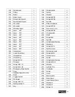
Page 25: ... Control Knob 1 181 Toggle Switch 1 182 PC Board 1 184 Screw M5 10 1 185 Spring washer 5 1 187 Key 1 188 Small spacer 1 190 Spring 2 192 Washer 4 193 Screw M8 55 2 194 Screw M4 38 1 195 Nut M4 1 196 Plate of tailstock 1 197 Screw M5 16 3 198 Base body cover 1 199 Screw M5 25 1 201 Chuck guard 1 202 Shaft 1 205 Screw M6 1 206 Nut M6 2 207 Compression Spring 1 208 Washer 6 2 209 Screw M3 4 4 210 Swi...

Page 26: ...70 Support Pin 1 272 Protective Cover 1 303 Washer 1 318 Screw M5 20 1 319 Washer 1 320 Screw M6 10 4 321 Screw M6 16 4 322 Key 1 323 Screw M8 25 3 324 Screw M4 8 2 325 Flange 1 326 Screw 2 327 Screw M6 8 1 ...

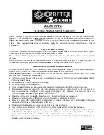
Page 27: ...r handy All returned merchandise will be subject to a minimum charge of 15 for re stocking and handling with the following qualifications Returns must be pre authorized by us in writing We do not accept collect shipments Items returned for warranty purposes must be insured and shipped pre paid to the nearest warehouse Returns must be accompanied with a copy of your original invoice as proof of pur...

Reviews: