background image


7


UNPACKING 


The dust collector is properly packaged in a 
carton for safe transportation. When 
unpacking, carefully inspect the carton and 
ensure that nothing has been damaged. 
 
While doing the inventory if you can not find 
any part, check if the part is already 
installed on the machine. 

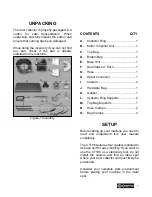
Figure-1 Inventory 


CONTENTS 


                         QTY


A. 

Collector Ring.................................... 1 

B. 

Motor / Impeller Unit .......................... 1 

C. 

Top Bag............................................. 1 

D. 

Bottom Bag ....................................... 1 

E. 

Base Unit........................................... 1 

F. 

Dual Intake 4” Each........................... 1 

G. 

Hose.................................................. 1 

H. 

Outlet Connector ............................... 1 

I. 

Casters.............................................. 4 

J. 

Hardware Bag ................................... 1 

K. 

Gasket............................................... 1 

L. 

Collector Ring Supports .................... 2 

M. 

Top Bag Supports ............................. 1 

N. 

Hose Clamps..................................... 2 

O. 

Bag Clamps....................................... 4 


SETUP 


Before setting up your machine you need to 
read and understand this user manual 
completely. 
 
The CT186 features four casters installed to 
its base unit for easy mobility. If you want to 
use the CT186 as a stationary tool, do not 
install the casters and find an ideal spot 
where your dust collector will most likely be 
positioned. 
 
Consider your complete work environment 
before placing your machine in the ideal 
spot. 

Summary of Contents for CT186

Page 1: ...MODEL CT186 2HP DUST COLLECTOR ...

Page 2: ... Instructions 4 Features 5 Physical Features 6 Unpacking 7 Setup 7 Proper Grounding 8 Assembly 9 Test Run 11 Operation 12 Maintenance 12 Bag Cleaning 12 Cleaning the Canister 12 Lubrication 12 Wiring Diagram 13 Parts Breakdown 13 Parts Diagram 14 Parts List 15 Warranty 16 ...

Page 3: ...3 ...

Page 4: ...4 ...

Page 5: ...faction The CT186 is a professional tool and like all power tools proper care and safety procedures should be adhered to Motor 2 HP Single Phase 220 Volt 9 5 Amps Switch ON OFF Switch with Removable Key Balanced Steel Impeller Yes Impeller Size 12 Collection Bag Volume 0 15 Cubic Meter Upper Bags One Micron Upper Filtration Bag Intakes Two 4 Overall Dimension L 34 850mm x W 22 560mm x H 73 1860mm ...

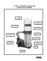
Page 6: ... 2 HP DUST COLLECTOR PHYSICAL FEATURES 1 Micron Filtration Bag Bag Clamp Collection Bag Collector Ring Outlet Connector Hose 2 Port Inlet Connector Casters Collector Support Rod 2 HP Motor Base Top Bag Support ...

Page 7: ...it 1 F Dual Intake 4 Each 1 G Hose 1 H Outlet Connector 1 I Casters 4 J Hardware Bag 1 K Gasket 1 L Collector Ring Supports 2 M Top Bag Supports 1 N Hose Clamps 2 O Bag Clamps 4 SETUP Before setting up your machine you need to read and understand this user manual completely The CT186 features four casters installed to its base unit for easy mobility If you want to use the CT186 as a stationary too...

Page 8: ...8 ...

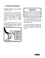
Page 9: ... a 3 prong grounded receptacle as shown in figure 2 Do not remove the grounding prong to fit it into a 2 pronged outlet Figure 2 220 Volts outlet for CT186 It is strongly recommended not to use extension cords with your CT186 Always try to position your machine close to the power source so that you do not need to use extension cords In case if you really find it necessary to use an extension cord ...

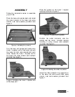
Page 10: ...r Secure the motor impeller unit to the base unit using screws and washers provided See figure 4 Figure 4 Installing the motor impeller unit on the base unit Place the gasket on the motor impeller opening as shown in figure 5 Figure 5 Positioning the gasket Position the outlet connector onto the gasket and the motor impeller opening securing it using screws and washers provided See figure 6 Figure...

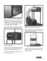
Page 11: ...ling collector ring and the upper bag support rod Take the hose provided and attach it with its one to the outlet connector and the other end to the collector ring See figure 9 Use the hose clamps provided to secure the hose on both ends Figure 9 Connecting the hose from the outlet connector to the collector ring Hang the top bag from the support and install it around the collector ring Secure it ...

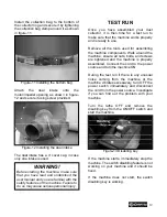
Page 12: ...ned and the machine is properly assembled Connect the cord to the power source and turn the machine ON During the test run if there is any unusual noise coming from the machine or the machine vibrates excessively turn OFF the power switch immediately and disconnect the cord from the power source Investigate if you can find out the problem with your machine Turn the lathe OFF and remove the disabli...

Page 13: ...ce Make sure you are wearing a respirator or dust mask while emptying the collection bag The tiny dust particles in the air can be inhaled easily and is very injurious to health Uninstall the clamp securing the collection bag around the collector ring Remove the collection bag and empty it Re install the bag and clamp it CLEANING THE CANISTER If using a canister The canister has a cleaning handle ...

Page 14: ...14 ...

Page 15: ...15 ...

Page 16: ...16 ...

Page 17: ...r handy All returned merchandise will be subject to a minimum charge of 15 for re stocking and handling with the following qualifications Returns must be pre authorized by us in writing We do not accept collect shipments Items returned for warranty purposes must be insured and shipped pre paid to the nearest warehouse Returns must be accompanied with a copy of your original invoice as proof of pur...

Reviews: