background image


  Figure 1-172 


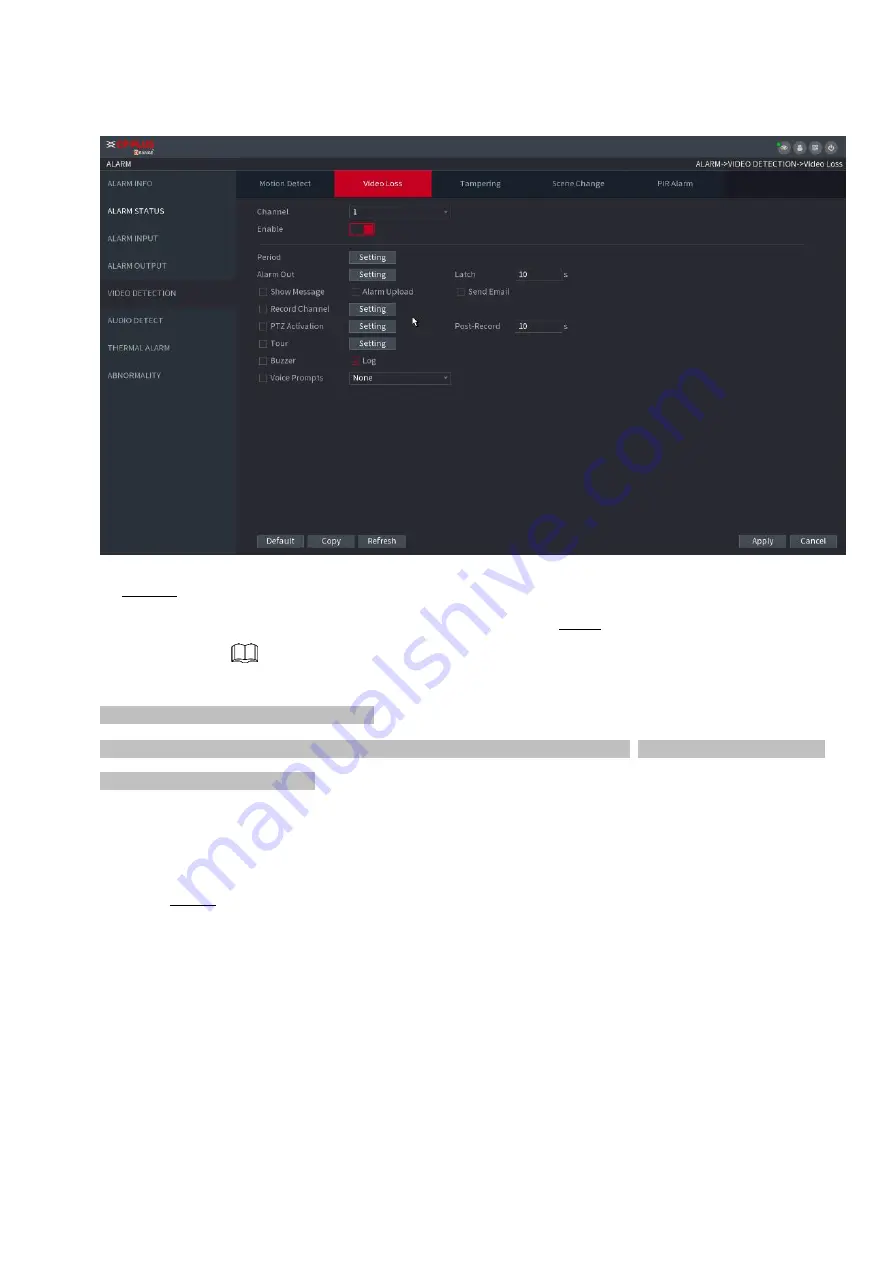
  Step 2   To configure the settings for the video loss detection parameters, see "1.8.5.1 Motion  Detect." 

  The video loss function does not have region and sensitivity items.  Step 3  Click 

Apply 

to complete the 

settings. 


Click 

Default 

to restore the default setting. 


Click 

Copy

, in the 

Copy 

dialog box, select the additional channel(s) that you want  to copy the motion detection 

settings to, and then click 

Apply

1.8.5.4  Scene Change 


  When the detected scene has changed, system can generate an alarm. 


Step 1 Select 

Main Menu>ALARM >VIDEO DETECTION >SCENE CHANGE

The 

Scene Change 

interface is displayed. See Figure 1-173. 

Summary of Contents for Orange

Page 1: ...Network Video Recorder User s Manual V1 0 ...

Page 2: ... potential hazard which if not avoided will result in death or serious injury WARNING Indicates a medium or low potential hazard which if not avoided could result in slight or moderate injury CAUTION Indicates a potential risk which if not avoided could result in property damage data loss lower performance or unpredictable result TIPS Provides methods to help you solve a problem or save you time N...

Page 3: ...en notice The product updates might cause some differences between the actual product and the manual Please contact the customer service for the latest program and supplementary documentation There still might be deviation in technical data functions and operations description or errors in print If there is any doubt or dispute please refer to our final explanation Upgrade the reader software or t...

Page 4: ...uliginous area Keep its horizontal installation or install it at stable places and prevent it from falling Do not drip or splash liquids onto the device do not put on the device anything filled with liquids in order to prevent liquids from flowing into the device Install the device at well ventilated places do not block its ventilation opening Use the device only within rated input and output rang...

Page 5: ...device Otherwise the user shall undertake resulting personnel injuries or device damages Use power supply that meets SELV safety extra low voltage requirements and supply power with rated voltage that conforms to Limited Power Source in IEC60950 1 For specific power supply requirements please refer to device labels Products with category I structure shall be connected to grid power output socket w...

Page 6: ...CE 70 1 3 4 SEQUENCE 76 1 3 5 TEST TEMPERATURE 78 1 4 PTZ 78 1 5 RECORD FILE 87 1 6 PLAYBACK AND SEARCH 87 1 7 AI 99 1 12 SETTING THE MOTION DETECTION REGION 142 1 12 SETTING PERIOD 144 1 9 POS 159 1 10 OPERATION AND MAINTENANCE 163 1 19 FILE BACKUP 177 1 19 STORAGE 199 1 19 SYSTEM 208 1 19 ACCOUNT 213 1 16 OUTPUT AND DISPLAY 220 1 19 AUDIO 225 1 18 USB DEVICE AUTO POP UP 230 1 19 SHUTDOWN 231 2 W...

Page 7: ... stable current if necessary UPS is a best alternative measure Step 1 Connect the device to the monitor and then connect a mouse Step 2 Connect power cable Step 3 Click the power button at the front or rear panel and then boot up the device After device booted up the system is in multiple channel display mode by default 1 1 2 Device Initialization If it is your first time to use the device set a l...

Page 8: ...Table 1 4 in 1 1 4 1 2 Date and Time for detailed information Clickto shut down the device It is suitable for the system integrator or the user to shut down directly after setting the time zone Step 3 Click Next The Device Initialization interface is displayed See Figure 1 2 Figure 1 2 ...

Page 9: ...rompt Question In the Prompt Question box enter the information that can remind you of the password On the login interface click the prompt will display to help you reset the password For your device own safety create a strong password of your own choosing We also recommend you change your password periodically especially in the high security system Step 5 Click Next The Unlock Pattern interface i...

Page 10: ...can reset the password through the reserved email address or security questions For details about resetting the password see 1 1 3 Reset Password If you do not want to configure the settings disable the email address and security questions functions on the interface Table 1 2 Password Protection Mode Description Email Address Enter the reserved email address In the Email Address box enter an email...

Page 11: ...is enabled you can use mobile phone to scan the QR code to reset the password For details see 1 1 3 2 Resetting Password on Local Interface If the password reset function is disabled there are two situations If you configured security questions you can reset the password by the security questions If you did not configure the security questions you can only use the reset button on the mainboard to ...

Page 12: ... main board You can only answer the security question on the local menu to reset password Make sure you have set security questions 1 1 3 2 Resetting Password on Local Interface Step 1 Enter the SYSTEM LOGIN interface If you have configured unlock pattern the unlock pattern login interface is displayed See Figure 1 6 Click Forgot Pattern the password login interface is displayed See Figure 1 7 If ...

Page 13: ...ss the Prompt interface is displayed See Figure 1 8 If you did not set the reserved email address the email entering interface is displayed See Figure 1 9 Enter the email address and then click Next the Prompt message interface is displayed See Figure 1 8 Figure 1 8 ...

Page 14: ...layed See Figure 1 10 After clicking Next the system will collect your information for password reset purpose and the information includes but not limited to email address MAC address and device serial number Read the prompt carefully before clicking Next Figure 1 10 ...

Page 15: ...rface Use the security code received in your email box to reset the password within 24 hours otherwise the security code becomes invalid Security questions On the Reset password interface as shown in Figure 1 11 in the Reset Type list select Security Questions the Security Questions interface is displayed If you did not configure the security questions before in the Reset Type list there is no Sec...

Page 16: ... enter the new password and enter it again in the Confirm Password box Step 7 Click Save The password resetting is complete A pop up message is displayed asking if you want to sync the password with the remote devices See Figure 1 13 Figure 1 13 ...

Page 17: ... again Step 3 Press and hold the reset button for 5 seconds to 10 seconds See Figure 1 14 for the location of the reset button Figure 1 14 Step 4 Reboot the Device After the Device is rebooted the settings have been restored to the factory default You can start resetting the password 1 1 4 Quick Settings After you successfully initialized the device it goes to startup wizard Here you can quickly c...

Page 18: ...The collected information is only used to verify the legality of the Device and push upgrade notices If you cancel the Auto check for updates check box the system will not perform automatic checks 1 1 4 1 General You can set NVR basic information such as system date holiday and etc You can also configure general settings by selecting Main Menu SYSTEM General 1 1 4 1 1 General You can set device ba...

Page 19: ...ne Instant Play Min In the Instant Play box enter the time length for playing back the recorded video The value ranges from 5 to 60 On the live view control bar click the instant playback button to play back the recorded video within the configured time Auto Logout Min In the Auto Logout box enter the standby time for the Device The Device automatically logs out when it is not working for the conf...

Page 20: ...is displayed Mouse Sensitivity Adjust the speed of double click by moving the slider The bigger the value is the faster the speed is Step 3 Click Next button to save settings 1 1 4 1 2 Date and Time You can set device time You can enable NTP Network Time Protocol function so that the device can sync time with the NTP server You can also configure date and time settings by selecting Main Menu SYSTE...

Page 21: ...ng Time function Click Week or click Date Start Time Configure the start time and end time for the DST End Time NTP Enable the NTP function to sync the Device time with the NTP server Server In the Server box enter the IP address or domain name of the corresponding NTP server Click Manual Update the Device starts syncing with the server immediately Port The system supports TCP protocol only and th...

Page 22: ... Figure 1 18 Step 2 Click Add Holidays button the Add Holidays interface is displayed See Figure 1 19 Figure 1 19 Step 3 Set holiday name repeat mode and holiday mode ...

Page 23: ...Next button to save settings 1 1 4 2 Basic Network Settings You can set device IP address DNS Domain Name System information You can also configure basic network settings by selecting Main Menu NETWORK TCP IP 1 12 Preparation Make sure the device has properly connected to the network Step 1 Click Next The TCP IP interface is displayed See Figure 1 20 Different series products have different Ethern...

Page 24: ...nce Two Ethernet ports share one IP address Normally only one Ethernet port is working and when this port fails the other port will start working automatically to ensure the network connection When testing the network status the network is regarded as offline only when both of the two Ethernet ports are disconnected The two Ethernet ports are used under the same LAN Load Balance Two network cards ...

Page 25: ...nfiguration IP Address Enter the IP address and configure the corresponding subnet mask and default gateway IP address and default gateway must be in the same network segment Subnet Mask Default Gateway DNS DHCP Enable the DHCP function to get the DNS address from router Preferred DNS In the Preferred DNS box enter the IP address of DNS Alternate DNS In the Alternate DNS box enter the IP address o...

Page 26: ...he normal speed For IPv6 version the IP address default gateway preferred DNS alternate DNS is 128 digit Fill in all items here This function is for some series product only Step 6 Click Next to complete the settings 1 1 4 3 INSTAON CLOUD Scan the QR code download the App to the cell phone you can use the smart phone to add the device Scan the QR code on the actual interface to download the cell p...

Page 27: ...MAC address and device serial number Step 3 Click Next button to complete setup The status is online if the INSTAON CLOUD registration is successful Client Operation Step 1 Use your cell phone to scan the QR code under Cell Phone Client to download the application Step 2 On your cell phone open the application and then tap Step 3 The menu is displayed You can start adding the device 1 Tap Device M...

Page 28: ...d 3 Tap OK If the Device has not been initialized Tap Device Initialization to perform initializing by following the onscreen instructions If the Device has been initialized you can start adding it directly 4 Tap Add Device The Add Device interface is displayed See Figure 1 24 You can add wireless device or wired device The Manual takes adding wired device as an example Figure 1 24 ...

Page 29: ...e is displayed See Figure 1 25 Figure 1 25 6 Enter a name for the NVR the username and password scan the QR code under Device SN 7 Tap Start Live Preview The Device is added and displayed on the live view interface of the cell phone See Figure 1 26 ...

Page 30: ...ams of the remote device You can view browse play back and manage several remote devices at the same time Step 1 On the INSTAON CLOUD interface click Next button The REGISTRATION interface is displayed See Figure 1 27 There are two ways to go to Registration interface Select Main Menu CAMERA ADD IP Cam Add IP cam you can go to the Camera Registration interface On the preview interface right click ...

Page 31: ...searched devices at the upper pane 2 Double click a remote device or select a remote device and then click Add to register it to the Added Device list See Figure 1 28 Refer to 3 Table 1 7 to set parameters The search results do not display the remote camera that has registered to the system ...

Page 32: ... IPC Display the front end devices DVR Display all storage devices such as NVR DVR and HCVR OTHER Display the devices that do not belong to IPC or DVR type Searched Device List Displays the searched devices You can view the device information such as status IP address Device Search Click Device Search the searched devices display in the searched device list To adjust the display sequence in the ti...

Page 33: ... information Delete Select the check box of the added device and then click Delete to delete the added device Import Select the searched devices and then click Import to import the devices in batches Export Select the added devices and then click Export The exported devices information is saved into the USB storage device Manual Add 1 Click Manual Add The Manual Add interface is displayed See Figu...

Page 34: ...evice Password Enter the password of the user for the remote device Remote Channel Enter the remote channel number of the remote device that you want to add Decoder Buffer In the Decoder Buffer list select Default Realtime or Fluent Protocol Type If the remote device is added through private protocol the default type is TCP If the remote device is added through Onvif protocol the system supports A...

Page 35: ...shot image at the specified time Select Main menu STORAGE SCHEDULE you can go to the SCHEDULE interface 1 1 4 5 1 Recording Schedule After set schedule record device can record video file according to the period you set here For example the alarm record period is from 6 00 18 00 Monday device can record alarm video files during the 6 00 18 00 All channels are record continuously by default You can...

Page 36: ...ns for different channels Select All if you want to set for all channels See Table 1 9 Table 1 9 Parameter Description Channel In the Channel list select a channel to record the video Pre record In the Pre record list enter the amount of time that you want to start the recording in advance ...

Page 37: ...is for some series products only The redundant HDD only back up the recorded videos but not snapshots Parameter Description ANR You can set ANR auto network resume function The IPC continues record once the NVR and IPC connection fails After the network becomes normal the NVR can download record file during the offline period from the IPC It is to guarantee there is no record loss on current conne...

Page 38: ...n when corresponding alarm occurs For example when the alarm type is MD select Main Menu ALARM VIDEO DETECTION Motion Detect select the record channel and enable record function See Figure 1 35 When the record type is MD motion detect alarm MD Alarm IVS and POS refer to 1 8 5 Video detect 1 8 3 Alarm 1 7 2 4 IVS and Step 3 POS for detailed information ...

Page 39: ...ou can set the record period for the holiday Figure 1 36 Define the period by drawing 1 Select a corresponding date to set Define for the whole week Click next to All all the icon switches to you can define the period for all the days simultaneously Define for several days of a week Click before each day one by one the ...

Page 40: ...w stands for MD motion detection record Red stands for alarm record Blue stands form intelligent record Orange stands for MD Alarm record Purple stands for POS record Once the time period overlaps the record priority MD Alarm Alarm POS Intelligent MD General Select a record type and then click the of the corresponding date to clear the corresponding period Figure 1 37 The MD record and alarm recor...

Page 41: ... so that the record plan can become activated Refer to 1 Record control for detailed information 1 1 4 5 2 Snapshot Schedule You can set schedule snapshot period After set schedule snapshot device can snapshot image according to the period you set here For example the alarm snapshot period is from 6 00 18 00 Monday device can snapshot during the 6 00 18 00 when an alarm occurs Step 1 Click Snapsho...

Page 42: ...pe is MD motion detect alarm MD Alarm IVS and POS enable the channel record function when corresponding alarm occurs For example when the alarm type is MD select Main Menu ALARM VIDEO DETECTION Motion Detect select the record channel and enable record function See Figure 1 35 When the record type is MD motion detect alarm MD Alarm IVS and POS refer to 1 8 5 Video detect 1 8 3 Alarm 1 7 2 4 IVS and...

Page 43: ... and snapshot function so that system can automatically record or snapshot Auto System automatically records at the type and record period you set in Schedule interface Manual System records general files for all day You need to have storage authorities to implement the Manual record operation Make sure the HDD has been properly installed Step 1 Right click mouse and then select Manual Record or s...

Page 44: ......

Page 45: ...t a single channel or select All Record status Auto Automatically record according to the record type and recording time as configured in the recording schedule Manual Keep general recording for 24 hours for the selected channel Off Do not record Snapshot status Enable or disable the scheduled snapshot for the corresponding channels Step 3 Click Apply ...

Page 46: ... storage the video file Different series products support different remote device amount Figure 1 43 1 2 1 1 Changing IP address Step 1 Select Main Menu REGISTRATION Camera Registration check the box before the camera name and then click Modify IP or click the before the camera name Enter Modify IP interface See Figure 1 44 Check the box before several cameras change the IP addresses of several ca...

Page 47: ...s of the IP address one by one to automatically allocate the IP addresses If there is IP conflict when changing static IP address device pops up IP conflict dialogue box If batch change IP address device automatically skips the conflicted IP and begin the allocation according to the incremental value Step 3 Input remote device user name and password When change IP addresses of several devices at t...

Page 48: ...265 Auto switch function Click H 265 Auto Switch button at the bottom of the interface it is from to The function is enabled See Figure 1 45 Figure 1 45 1 2 1 2 IP Export Device can export the Added device list to your local USB device Step 1 Insert the USB device and then click the Export button The Browse interface is displayed See Figure 1 46 ...

Page 49: ...P address the File Backup Encryption check box is checked by default The file information includes IP address port channel number manufacturer user name and password If you select the File Backup Encryption check box the file format is backup If you clear the File Backup Encryption check box the file format is csv In this case there might be a risk of data leakage ...

Page 50: ... 2 Remote Device Initialization Remote device initialization can change remote device login password and IP address When connect a camera to the NVR via PoE port NVR automatically initialize the camera The camera adopts NVR current password and email information by default When connect a camera to the NVR via PoE port after NVR upgraded to the new version the NVR may fail to initialize the camera ...

Page 51: ...vice password and email information If you want to use current device password and email information the remote device automatically uses NVR admin account information login password and email There is no need to set password and email Go to step 6 1 Cancel Using current device password and email info The Enter Password interface is displayed See Figure 1 49 ...

Page 52: ... Figure 1 49 ...

Page 53: ...n Confirm Password For your device own safety create a strong password of your own choosing We also recommend you change your password periodically especially in the high security system Step 5 Click Next button The Password Protection interface is displayed See Figure 1 50 Figure 1 50 Step 6 Set email information Input an email address for reset password purpose Cancel the box and then click Next...

Page 54: ...everal devices IP addresses at the same time input incremental value Device can add the fourth address of the IP address one by one to automatically allocate the IP addresses If there is IP conflict when changing static IP address device pops up IP conflict dialogue box If batch change IP address device automatically skips the conflicted IP and begin the allocation according to the incremental val...

Page 55: ...p 1 2 3 Short Cut Menu to Register Camera If you have not registered a remote device to a channel go to the preview interface to add Step 1 On the Preview interface Move your mouse to window There is an icon on the channel window See Figure 1 53 Figure 1 53 ...

Page 56: ...on for detailed information 1 2 4 Image You can set network camera parameters according to different environments It is to get the best video effect Step 1 Select Main Menu CAMERA IMAGE The IMAGE interface is displayed See Figure 1 54 Figure 1 54 Step 2 Configure parameters See Table 1 11 ...

Page 57: ...ge edge The bigger the value is the more obvious the image edge is Adjusts the sharpness according to actual environment Gamma It is to adjust image brightness and enhance the image dynamic display range The bigger the value is the brighter the video is Mirror Enable the function the left and right side of the video image will be switched It is disabled by default This function is for some series ...

Page 58: ...ct the image whole hue so that the image can accurately displays the environment status Different cameras support different WB modes such as auto manual natural light outdoor etc Day Night Configure the color and black white mode of the image This setting is not affected by the configuration files The default setting is Auto Color The camera outputs color image only Auto Depends on the camera such...

Page 59: ... This function can reduce the video bit stream for non important recorded video to maximize the storage space Enabled Disabled Type Main Stream In the Type list select General MD Motion Detect or Alarm Sub Stream This setting is not configurable Compression In the Compression list select the encode mode H 265 Main profile encoding This setting is recommended H 264H High profile encoding Low bit st...

Page 60: ...n select the value from 1 through 30 However the actual range of frame rate that you can select depends on the capability of the Device Bit Rate Type In the Bit Rate Type list select CBR Constant Bit Rate or VBR Variable Bit Rate If you select CBR the image quality cannot be configured if you select VBR the image quality can be configured Quality This function is available if you select VBR in the...

Page 61: ...dio and video stream Audio Format In the Audio Format list select a format G711a G711u PCM AAC Audio Sampling In the Audio Sampling list you can select audio sampling rate Step 5 Click OK Back to Encode interface Step 6 Click Apply 1 2 5 2 Snapshot You can set snapshot mode image size quality and interval Step 1 Select Main menu CAMERA ENCODE Snapshot The SNAPSHOT interface is displayed See Figure...

Page 62: ... alarm event occurs such as motion detection event video loss and local alarms Image Size In the Image Size list select a value for the image The bigger the value is the better the image will become Image Quality Configure the image quality by 6 levels The higher the level is the better the image will become Interval Configure or customize the snapshot frequency Max supports 3600 seconds image Ste...

Page 63: ... The Upgrade interface is displayed See Figure 1 59 Figure 1 59 Step 2 Update the firmware of the connected remote device Online Upgrade 1 Select a remote device and then click the Detect button on the right side or check a box to select a remote device and then click Manual Check System detects the new version on the cloud 2 Select a remote device that has new version and then click online upgrad...

Page 64: ...are too much remote devices select Device Type from the drop down list to search the remote device you desire 1 2 8 Remote Device Info 1 2 8 1 Device Status You can view the connection and alarm status of the corresponding channel Select Main Menu CAMERA REGISTRATION Status the Status interface is displayed See Figure 1 60 Refer to Table 1 15 for detailed information Figure 1 60 ...

Page 65: ...e interface is displayed See Figure 1 61 Figure 1 61 1 3 Live View After you logged in the system goes to multiple channel live view mode by default You can view the monitor video of each channel The displayed window amount may vary The actual product shall prevail Icon Description Icon Description IPC works properly IPC does not support There is an alarm Video loss occurs ...

Page 66: ...l is in monitor lock status system displays this icon 5 When the device connects to the network camera remotely system displays this icon This function is for some series products only 1 3 2 Navigation bar You can quickly perform operation through the icon on the navigation bar Different series products may display different navigation bar icons Refer to the actual product for detailed information...

Page 67: ...lor Setting interface For details see 1 4 2 PTZ Control This function is supported only in single channel layout Open the record search interface For detail see 1 6 2 Search Interface Open the Broadcast interface For detail see 1 17 3 Broadcast Open the EVENT interface to view the device alarm status For details see 1 8 2 Alarm Status Open the CHANNEL INFO interface to display the information of e...

Page 68: ... can view its status such as alarm status record status connection status record mode etc Alarm status It includes motion detection alarm video loss alarm tampering alarm Record status System is recording or not Bit Rate System displays bit rate information Status current channel connection status Click button system goes to the channel information setup interface You can view information of the c...

Page 69: ... USB device or update NVR system Click system goes to HDD Manager interface You can view and manage HDD information See Figure 1 64 Here you can view USB information backup file and update system Refer to 1 11 File Backup 1 10 1 Log 1 10 4 2 IMP EXP 1 10 4 4 System Update for detailed information ...

Page 70: ... the video of current channel you can see system pops up the preview control interface See Figure 4 65 If your mouse stays in this area for more than 6 seconds and has no operation the control bar automatically hides Slight difference may be found on the user interface Figure 1 65 ...

Page 71: ...h as channel name and recording status icon are shielded during instant playback and will not display until exited During playback screen split layout switch is not allowed Tour high higher priority than the instant playback The instant playback function is null when tour function is in process and the preview control interface auto hides either The function becomes valid again after tour is compl...

Page 72: ...1 3 3 2 Digital zoom Figure 1 67 ...

Page 73: ...g the image toward any direction to view the other enlarged areas Right click mouse to cancel zoom and go back to the original interface Figure 1 68 1 3 3 3 Instant backup You can record the video of any channel and save the clip into a USB storage device By clicking the recording is started To stop recording click this icon again The clip is automatically saved into the connected USB storage devi...

Page 74: ...e network bandwidth suitable for video wall surveillance storage etc S Sub stream Its definition is low but occupies small network bandwidth It is suitable for general surveillance remote connection etc Click to switch the bit stream type of the main stream and sub stream M Main stream S Sub stream Some series products support two sub streams S1 S2 Refer to 1 2 5 1 Encode for detailed information ...

Page 75: ...ence View Layout Set customized screen split mode and channels For details see 1 3 4 Sequence Previous Screen Click Previous Screen to go to the previous screen For example if you are using 4 split mode the first screen is displaying the channel 1 4 click Next screen you can view channel 5 8 Next Screen Camera Registration Open the CAMERA REGISTRATION interface For details see 1 1 4 4 Registration...

Page 76: ...t The preview layout restores default channel layout after Default operation Step 1 On the preview interface right click mouse and then click Sequence The Sequence interface is displayed See Figure 1 70 Enter edit view interface device automatically switches to the max split amount mode The channel list on the edit view interface displays the added camera channel number and channel name means came...

Page 77: ...he channel to the desired window or drag on the preview window to switch the position Check the channel number at the right bottom corner to view the current channel sequence See Figure 1 71 Figure 1 71 Step 3 Click Apply to save current channel sequence ...

Page 78: ...nstant temperature This function may collect the human temperature in the surveillance video be careful This function is for some series products only Preparations Refer to 1 16 1 Display to enable test temperature function On the preview window click any position on the thermal channel video The interface is shown as below See Figure 1 76 1 4 PTZ PTZ is a mechanical platform that carries a camera...

Page 79: ... you use local PTZ make sure you have set PTZ protocol otherwise you cannot control the local PTZ Local The PTZ device connects to the NVR via the cable Remote The PTZ device connects to the NVR via the network This function is for some series products only Step 1 Select Main menu CAMERA PTZ Step1 The PTZ interface is displayed Figure 1 82 Remote Figure 1 82 Step 2 Configure parameters See Table 1...

Page 80: ...amera otherwise the system cannot control PTZ camera Baud rate In the Baud rate list select the baud rate for the PTZ camera The default is 9600 Data Bits The default is 8 Stop Bits The default is 1 Parity The default is NONE Step 3 Click Apply 1 4 2 PTZ Control PTZ control panel performs the operations such as directing camera in eight directions adjusting zoom focus and iris settings and quick p...

Page 81: ...middle of the screen Zooming On the fast positioning screen drag to draw a square on the view The square supports zooming Dragging upward is to zoom out and dragging downward is to zoom in The smaller the square the larger the zoom effect This function is for some series products only and can only be controlled through mouse operations Click you can control the four directions left right up and do...

Page 82: ...ction Icon Function Preset Auto Pan Tour Flip Pattern Reset Auto scan Click the AUX Config icon to open the PTZ functions settings interface AUX Switch Click the Enter Menu icon to open the MENU OPERATION interface 1 4 3 Configuring PTZ Functions 1 4 3 1 Configuring Presets Step 1 On the Expanded PTZ Control Panel click The Preset interface is displayed See Figure 1 86 ...

Page 83: ...ete the preset settings 1 4 3 2 Configuring Tours Step 1 On the Expanded PTZ Control Panel click The PTZ interface is displayed Step 2 Click the Tour tab The Tour tab is displayed See Figure 1 87 Figure 1 87 Step 3 In the Patrol No box enter the value for the tour route Step 4 In the Preset box enter the preset value Step 5 Click Add Preset A preset will be added for this tour ...

Page 84: ...tern interface is displayed See Figure 1 88 Figure 1 88 Step 3 In the Pattern box enter the value for pattern Step 4 Click Start to perform the directions operations You can also go to the PTZ Control Panel to perform the operations of adjusting zoom focus iris and directions Step 5 On the PTZ interface click End to complete the settings 1 4 3 4 Configuring Auto Scan Step 1 On the Expanded PTZ Con...

Page 85: ...toring from the Expanded PTZ Control Panel See Figure 1 90 Figure 1 90 1 4 4 1 Calling Presets Step 1 On the Expanded PTZ Control Panel in the No box enter the value of the preset that you want to call Step 2 Click to call the preset Step 3 Click again to stop calling the preset 1 4 4 2 Calling Tours Step 1 On the Expanded PTZ Control Panel in the No box enter the value of the tour that you want ...

Page 86: ...nel in the No box enter the value of the border that you want to call Step 2 Click The PTZ camera performs scanning according to the configured borders Step 3 Click again to stop auto scanning 1 4 4 5 Calling Auto Pan Step 1 On the Expanded PTZ Control Panel click to start moving in horizontal direction Step 2 Click again to stop moving 1 4 4 6 Using AUX Button On the Expanded PTZ Control Panel cl...

Page 87: ...1 6 1 Instant Playback You can view the record file of previous 5 to 60 minutes Refer to 4 3 2 Navigation bar for instant playback information 1 6 2 Search Interface You can search and playback the record fine on the NVR Select Main Menu PLAYBACK or on the preview interface right click mouse and then select Search you can go to the following interface See Figure 1 92 The following figure for refer...

Page 88: ...tton to select the area that you want to enlarge The area is enlarged after the left mouse button is released To exit the enlarged status right click on the image 2 Playback Controls Bar Playback control buttons Refer to 1 6 2 1 Playback Control for detailed information Clip Click to edit the record file and then save specified footages Refer to 1 6 2 3 Clip for detailed information Backup Click t...

Page 89: ...f different channels in the same period in multi channel view Record type Select the check box to define the recording type to search for 5 Search type Select the content to play back Record PIC Splice Playback For details about the selecting search type refer to 1 6 2 2 Search Type for detailed information 6 Calendar Click the date that you want to search the time bar displays the corresponding r...

Page 90: ...n s or playbac k speeds 1 6 2 1 Playback Control The playback control interface is shown as below See Figure 1 93 Figure 1 93 Refer to the following sheet for more information See Table 1 24 Table 1 24 Icon Function Play Pause In slow play mode click it to switch between pla Stop When playing back click to stop current playbac Backward play In normal play mode left click the button th play Click i...

Page 91: ...r to 1 6 4 Mark Playback for detailed information Display hide POS information In 1 channel playback mode you can click it to display hide POS information on the video In 1 channel playback mode click it to enable disable display IVS rule information on the video This function is for some series only 1 6 2 2 Search Type You can search the recorde d videos splice or snapsh ots from HDD or external ...

Page 92: ...ip file Figure 1 96 Clip function is for one channel multiple channel Max save 1024 files at the same time This function is not for the file already checked in the file list 1 6 2 4 Record Backup This function is to backup files you checked in the file list or the file you just clip Step 1 Select the recorded video file that you want to back up You can select the following two types of files Recor...

Page 93: ... Step 3 Click Backup to begin the process 1 6 3 Smart Search Playback Figure 1 97 ...

Page 94: ...art search and playback System is going to playback all motion detects record footages Step 4 Click again to stop smart search function The motion detect region cannot be the full screen zone The motion detect region adopts the current whole play pane by default Selects the other file on the list system begins playing the motion detect footages of another file The time bar unit switch backward pla...

Page 95: ... N seconds of the mark time Usually system can playbacks previous N seconds record if there is such kind of record file Otherwise system playbacks from the previous X seconds when there is such as kind of record Mark Manager Click the mark manager button on the Search interface Figure 1 92 you can go to Manager interface See Figure 1 99 System can manage all the record mark information of current ...

Page 96: ... Figure 1 99 ...

Page 97: ...s listed below Step 1 Select Main Menu PLAYBACK or on the preview window right click mouse and then click Search you can go to the Search interface Step 2 At the top right corner select image and then input playback interval Step 3 Select date and channel click to play 1 6 6 Splice Playback You can clip the recorded video files into splices and then play back at the same time to save your time Thi...

Page 98: ...ure 1 102 Figure 1 102 Check a file name double click the file or click to play Input accurate time at the top column you can search records of current day System max displays 128 record files in one list Click to go back to the calendar channel selection interface Lock or Unlock File To lock the recorded video on the File List interface select the check box of the recorded video and then click Th...

Page 99: ... any zone on the screen you can zoom in current zone Right click mouse to exit 1 6 8 2 Switch Channel During playback mode select from the dropdown list to switch playback channel The smart search channel does not support this function either When system is playing back the record file click the number button at the front panel system begins playing the record file of selected channel dated the sa...

Page 100: ...cted faces and play back Step 1 Select Main Menu AI SMART SEARCH FACE DETECTION The FACE DETECTION interface is displayed See Figure 1 104 Figure 1 104 Step 2 Select the channel enter the start time and end time and set for the gender age glasses beard and mask Click Smart Search The results are displayed See Figure 1 105 For privacy reason the human face in the image is pixelated The actual image...

Page 101: ...s to the external storage device select files click Backup select the save path and file type and then click Start See Figure 1 106 Figure 1 106 To lock the files to make it unable to be overwritten select the files and then click Lock To add a mark to the file select the files and then click Add Mark Go to Face Properties and Person Details to view detailed information 1 7 1 2 Face Recognition ...

Page 102: ...earching byAttributes Step 1 Select Main Menu AI SMART SEARCH FACE RECOGNITION Search by Attributes The Search by Attributes interface is displayed See Figure 1 107 Figure 1 107 Step 2 Select the channel and set the parameters such as start time end time gender age glasses beard mask and similarity according to your requirement Step 3 Click Smart Search The search result is displayed See Figure 1 ...

Page 103: ...lick Backup select the save path and file type and then click Start See To lock the files to make it unable to be overwritten select the files and then click Lock To add a mark to the file select the files and then click Add Mark Go to the Face Properties and Person Details to view detailed information 1 7 1 3 IVS You can search and playback the alarm record files Step 1 Select Main Menu AI SMART ...

Page 104: ...p select the save path and file type and then click Start To lock the files to make it unable to be overwritten select the files and then click Lock To add a mark to the file select the files and then click Add Mark Go to the Face Properties and Person Details to view detailed information 1 7 1 4 Human Body Detection You can search the human body and search the alarm record during the specified pe...

Page 105: ... 2 Select a channel start time end time and set corresponding parameters Step 3 Click Smart search The search result is displayed See Figure 1 113 For privacy reason the human face in the image is pixelated Figure 1 113 ...

Page 106: ...files and then click Lock To add a mark to the file select the files and then click Add Mark Go to the Face Properties and Person Details to view detailed information 1 7 1 5 Vehicle Detection You can search according to the vehicle parameters and search the alarm record during the specified period This function is for some series products only Step 1 Select Main Menu AI SMART SEARCH VEHICLE DETEC...

Page 107: ...ck Backup select the save path and file type and then click Start To lock the files to make it unable to be overwritten select the files and then click Lock To add a mark to the file select the files and then click Add Mark 1 7 1 6 Non motor Vehicle Detection You can search according to the non motor vehicle parameters and search the alarm record during the specified period This function is for so...

Page 108: ... Step 2 Select the channel and the time and then select one or multiple features from Type Vehicle Color People Number or Helmet Step 3 Click Smart Search The search result is displayed See Figure 1 116 Figure 1 116 ...

Page 109: ... To lock the files to make it unable to be overwritten select the files and then click Lock To add a mark to the file select the files and then click Add Mark 1 7 1 7 People Counting You can detect the people amount in the specified zone and display the statistics image Step 1 Select Main Menu AI SMART SEARCH PEOPLE COUNTING The PEOPLE COUNTING interface is displayed See Figure 1 117 Figure 1 117 ...

Page 110: ...Report Type Select report type from the dropdown list daily report monthly report yearly report Start time end time Set search start time and end time Type Select from the dropdown list 1 7 1 8 Heat map You can detect the active objects distribution in the monitor zone during the specified period and use different colors to display on the heat map report 1 7 1 8 1 Normal Step 1 Select Main Menu AI...

Page 111: ...tart time end time Step 3 Click Search Step 4 System display heat map report Click Export and then select path Click Save to save current report to the USB device 1 7 1 8 2 Fisheye Step 1 Select Main Menu AI SMART SEARCH HEAT MAP Fisheye The Fisheye interface is displayed See Figure 1 119 ...

Page 112: ...n face recognition human body detection people counting heat map If you do not set a rule here you cannot use these AI intelligent functions when you are connecting to a smart network camera This series NVR products support AI by camera only Make sure the connected network camera supports intelligent functions For NVR it just displays the intelligent alarm information from the smart network camera...

Page 113: ... number System displays different smart plan interfaces since the remote device may supports different functions 1 Select a channel 2 Select a preset 3 Click the smart plan icon at the bottom left The icon becomes highlighted 4 Click Apply ...

Page 114: ...omes blue highlighted 3 Click Apply 1 7 2 2 Face Detection The Device can analyze the pictures captured by the camera to detect whether the faces are on the pictures You can search and filter the recorded videos the faces and play back Preparations The connected camera shall support human face detection function Step 1 Select Main Menu AI PARAMETERS FACE DETECTION The FACE DETECTION interface is d...

Page 115: ...R Face RoI Check the box to enable Face RoI function system displays human face at the enhanced way Rule Click Setting to draw areas to filter the target You can configure two filtering targets maximum size and minimum size When the target is smaller than the minimum size or larger than the maximum size no alarms will be activated The maximum size should be larger than the minimum size Left click ...

Page 116: ...e activates the channel for recording You need to enable intelligent recording and auto recording first For details see 1 1 4 6 Schedule PTZ Activation Select the check box and click Setting to select the channel and PTZ action When an alarm occurs the NVR device associates the channel to perform the corresponding PTZ action For example activate the PTZ in channel one to turn to the preset point X...

Page 117: ...ace belongs to the library The comparison result will be displayed on the AI mode live view screen and smart search interface and link the alarms This series NVR products support AI by camera only You can use the connected camera to realize AI function Make sure the connected camera supports human face detection function Step 1 Select Main Menu AI PARAMETERS FACE RECOGNITION The FACE RECOGNITION i...

Page 118: ...mber is the easier the alarm linkage will trigger Step 7 Click to set the alarm linkage Step 8 Configure the parameters See Table 1 28 Table 1 28 Parameter Description Period Configure the period and in the set time range the corresponding configuration item will be linked to start the alarm Alarm Out The alarm device such as lights sirens etc is connected to the alarm output port When an alarm oc...

Page 119: ...period of time The time range is from 10 seconds to 300 seconds Tour Select the check box and select the channel for tour When an alarm occurs the local interface of the NVR device displays the selected channel screen You need to set the time interval and mode for tour first see 1 16 2 Tour After the tour is over the preview interface is restored to the screen split mode before the tour Log Select...

Page 120: ...l not be more than 10pixels 10 pixels The abandoned object size shall be more than 15pixels 15 pixels CIF resolution The object width shall not be more than 1 3 of the video height and width The recommended height is 10 of the video The object and the background brightness different shall be more than 10 grey levels The object shall remain on the video for more than 2 seconds The moving distance i...

Page 121: ...ight environment avoid direct sunlight Step 1 Select Main Menu AI PARAMETERS IVS The IVS interface is displayed See Figure 1 127 Figure 1 127 Step 2 Select a channel from the dropdown list Click Add and then set corresponding rule See Figure 1 128 Clickto delete the selected rule ...

Page 122: ...ck Apply 1 7 2 4 1 Tripwire When the detection target crosses the warning line along the set direction the system performs an alarm linkage action Step 1 Select Main Menu AI PARAMETERS IVS In the Type drop down list select Tripwire See Figure 1 129 Figure 1 129 ...

Page 123: ... Step 2 Draw the detection rule Clickto draw the rule on the surveillance video the system displays as Figure 1 130 Figure 1 130 1 Configure the parameters See Table 1 29 Table 1 29 ...

Page 124: ...pwire function 1 Press and hold down the left button on the monitor screen to draw the line The line can be a straight line or a curve 2 Click OK to complete the rule setting Step 3 Click System displays the Trigger interface Step 4 Configure the parameters See Table 1 30 Table 1 30 Parameter Description Period Configure the period and in the set time range the corresponding configuration item wil...

Page 125: ... 4 3 Configuring PTZ Functions Delay At the end of the alarm the recording extends for a period of time The time range is from 10 seconds to 300 seconds Tour Select the check box and select the channel for tour When an alarm occurs the local interface of the NVR device displays the selected channel screen You need to set the time interval and mode for tour first see 1 16 2 Tour After the tour is o...

Page 126: ... the amount has exceeded the threshold 1 7 2 5 1 People Counting Step 1 Select Main Menu AI PARAMETERS PEOPLE COUNTING PEOPLE COUNTING The PEOPLE COUNTING interface is displayed See Figure 1 148 Figure 1 148 Step 2 Configure parameters See Table 1 40 Table 1 40 Parameter Description Channel Select a channel from the dropdown list Enable Check the box to enable the function ...

Page 127: ...ime range is from 0 seconds to 300 seconds Alarm Upload Select the check box When an alarm occurs the NVR device uploads an alarm signal to the network including the alarm center This function is for some series products only You need to set the alarm center first For details see 4 12 9 Alarm Centre Send Email Select the check box When an alarm occurs the NVR device sends an email to the set mailb...

Page 128: ...hen select the corresponding audio file from the dropdown list System plays the audio file when the alarm occurs Refer to 4 17 1 File Manage to add audio file first Buzzer Select the check box to activate the buzzer when an alarm occurs Step 3 Click Apply to complete the setup 1 7 2 5 2 Queuing After connecting to the AI fisheye camera that supports the queuing function system can realize the corr...

Page 129: ... alarm center first For details see 4 12 9 Alarm Centre Send Email Select the check box When an alarm occurs the NVR device sends an email to the set mailbox to notify the user You need to set the email first For details see 4 12 6 Email Record Channel Select the check box and select the needed recording channel support multiple choices When an alarm occurs the NVR device activates the channel for...

Page 130: ...lect the corresponding audio file from the dropdown list System plays the audio file when the alarm occurs Refer to 4 17 1 File Manage to add audio file first Buzzer Select the check box to activate the buzzer when an alarm occurs Step 3 Click Apply to complete the setup 1 7 2 6 Heat map Heat map technology can monitor the active objects distribution status on the specified zone during a period an...

Page 131: ...eously Define the period by editing 1 Click the of the corresponding date and then set the period on the pop up interface Click OK to save There are six periods for you to set for each day Under Copy select All to apply the settings to all the days of a week or select specific day s that you want to apply the settings to 2 Click Apply to save the settings Step 5 Click Apply button to complete setu...

Page 132: ...t different plate recognition rule alarm linkage actions in different environments blacklist whitelist and regular Step 1 Select Main Menu AI PARAMETERS ANPR The ANPR interface is displayed See Figure 1 152 Figure 1 152 ...

Page 133: ...c is connected to the alarm output port When an alarm occurs the NVR device transmits the alarm information to the alarm device Latch When the alarm ends the alarm extended for a period of time The time range is from 0 seconds to 300 seconds Alarm Upload Select the check box When an alarm occurs the NVR device uploads an alarm signal to the network including the alarm center This function is for s...

Page 134: ...val and mode for tour first see 4 16 2 Tour After the tour is over the preview interface is restored to the screen split mode before the tour Log Select the check box the NVR device records the alarm information in the log when an alarm occurs Voice Prompts Check the box and then select the corresponding audio file from the dropdown list System plays the audio file when the alarm occurs Refer to 1...

Page 135: ...external storage device Select an alarm event log and then click Backup to back up it to peripheral USB device Select an alarm event log clickto play the recorded video of alarm event Double click a log or click Details to view the detailed information of the event 1 8 2 Alarm Status You can view NVR alarm event and remote channel alarm event Select Main Menu ALARM ALARM STATUS the ALARM STATUS in...

Page 136: ... the alarm input port to the NVR Network alarm NVR trigger corresponding alarm operations when it receives the alarm signal via the network transmission IPC external alarm When the network camera connected peripheral device has triggered an alarm it can upload the alarm signal to the NVR via the network transmission The system can trigger the corresponding alarm operations IPC offline alarm When t...

Page 137: ...arm Name Enter an alarm name Type NO normal open or NC normal close Period Define a period during which the alarm is active For details see Setting Period in 4 8 5 1 Motion Detect Alarm Out The alarm device such as lights sirens etc is connected to the alarm output port When an alarm occurs the NVR device transmits the alarm information to the alarm device Latch When the alarm ends the alarm exten...

Page 138: ...e channel and PTZ action When an alarm occurs the NVR device associates the channel to perform the corresponding PTZ action For example activate the PTZ in channel one to turn to the preset point X Tripwire alarm supports to activate PTZ preset point only You need to set the corresponding PTZ actions first see 1 4 3 Configuring PTZ Functions Delay At the end of the alarm the recording extends for ...

Page 139: ...t the alarm device to the system alarm output port and set the mode as auto system can trigger the corresponding operations when an alarm occurs Auto Once an alarm event occurs system can generate an alarm Manual Alarm device is always on the alarming mode Off Disable alarm output function Step 1 Select Main Menu ALARM ALARM OUTPUT The ALARM OUTPUT interface is displayed See Figure 1 166 Figure 1 ...

Page 140: ...n see motion detect interface See Figure 1 169 There are five detection types motion detection video loss tampering scene changing and PIR alarm 1 8 5 1 Motion Detect When the moving object appears and moves fast enough to reach the preset sensitivity value the system activates the alarm Step 1 Select Main Menu ALARM VIDIEO DETECTION Motion Detect The Motion Detect interface is displayed See Figur...

Page 141: ...nal to the network including the alarm center This function is for some series products only You need to set the alarm center first For details see 4 12 9 Alarm Centre Send Email Select the check box When an alarm occurs the NVR device sends an email to the set mailbox to notify the user You need to set the email first For details see 4 12 6 Email Record Channel Select the check box and select the...

Page 142: ...ENCODE Snapshot in the Mode list select Event Trigger Voice Prompts Check the box and then select the corresponding audio file from the dropdown list System plays the audio file when the alarm occurs Refer to 4 17 1 File Manage to add audio file first Buzzer Select the check box to activate the buzzer when an alarm occurs Step 3 Click Apply to save the settings Click Default to restore the default...

Page 143: ...ame for the region Sensitivity Every region of every channel has an individual sensitivity value The bigger the value is the easier the alarms can be activated Threshold Adjust the threshold for motion detect Every region of every channel has an individual threshold When anyone of the four regions activates motion detect alarm the channel where this region belongs to will activate motion detect al...

Page 144: ... the timeline click the half hour blocks to select the active period Define for several days of a week Click before each day the icon switches to On the timeline of any selected day click the half hour blocks to select the active periods all the days with will take the same settings Define for all days of a week Click All all switches to On the timeline of any day clicks the half hour blocks to se...

Page 145: ...ay s that you want to apply the settings to 3 Click OK to save the settings Step 3 On the Motion Detect interface click Apply to complete the settings 1 8 5 2 Tampering When the camera lens is covered or the video is displayed in a single color because of sunlight status the monitoring cannot be continued normally To avoid such situations you can configure the tampering alarm settings Step 1 Selec...

Page 146: ...o complete the settings Click Default to restore the default setting Click Copy in the Copy dialog box select the additional channel s that you want to copy the motion detection settings to and then click Apply 1 8 5 3 Video Loss When the video loss occurs the system activates the alarm Step 1 Select Main Menu ALARM VIDIEO DETECTION Video Loss The Video Loss interface is displayed See Figure 1 172...

Page 147: ...plete the settings Click Default to restore the default setting Click Copy in the Copy dialog box select the additional channel s that you want to copy the motion detection settings to and then click Apply 1 8 5 4 Scene Change When the detected scene has changed system can generate an alarm Step 1 Select Main Menu ALARM VIDEO DETECTION SCENE CHANGE The Scene Change interface is displayed See Figur...

Page 148: ...ene has changed system can generate an alarm PIR function helps enhancing the accuracy and validity of motion detect It can filter the meaningless alarms that are activated by the objects such as falling leaves flies The detection range by PIR is smaller than the field angle PIR function is enabled by default if it is supported by the cameras Enabling PIR function will get the motion detect to be ...

Page 149: ...k Copy in the Copy dialog box select the additional channel s that you want to copy the motion detection settings to and then click Apply 1 8 6 Audio Detect System can generate an alarm once it detects the audio is not clear the tone color has changed or there is abnormal or audio volume changes Step 1 Select Main Menu ALARM AUDIO DETECT The AUDIO DETECT interface is displayed See Figure 1 175 ...

Page 150: ...sier it is to trigger an alarm But at the same time the false alarm may occur The default value is recommended Threshold You can set intensity change threshold The smaller the value is the higher t sensitivity is Alarm Out The alarm device such as lights sirens etc is connected to the alarm output port When an alarm occurs the NVR device transmits the alarm information to the alarm device Latch Wh...

Page 151: ...e channel and PTZ action When an alarm occurs the NVR device associates the channel to perform the corresponding PTZ action For example activate the PTZ in channel one to turn to the preset point X Tripwire alarm supports to activate PTZ preset point only You need to set the corresponding PTZ actions first see 1 4 3 Configuring PTZ Functions Delay At the end of the alarm the recording extends for ...

Page 152: ...rature difference and cold hot alarm Fire alarm System generates an alarm once it detects there is a fire The alarm mode includes Preset and Excluded zone Temperature temperature difference System triggers an alarm once the temperature difference between two positions is higher or below the specified threshold Clod hot alarm System triggers an alarm once the detected position temperature is higher...

Page 153: ... Table 1 48 Table 1 48 Parameter Description Alarm Out The alarm device such as lights sirens etc is connected to the alarm output port When an alarm occurs the NVR device transmits the alarm information to the alarm device Latch When the alarm ends the alarm extended for a period The time range is from 0 seconds to 300 seconds Show Message Check box to enable a pop up message in your local host P...

Page 154: ...recording extends for a period The time range is from 10 seconds to 300 seconds Tour Select the check box and select the channel for tour When an alarm occurs the local interface of the NVR device displays the selected channel screen You need to set the time interval and mode for tour first see 1 16 2 Tour After the tour is over the preview interface is restored to the screen split mode before the...

Page 155: ... Figure 1 177 ...

Page 156: ... Figure 1 178 Figure 1 179 ...

Page 157: ...s a network event such as disconnection IP conflict MAC conflict See Figure 1 178 User Sets process method when there is an Illegal login event See Figure 1 179 Device Sets process method when fan speed is abnormal or there is a network security event See Figure 1 180 Different series products support different event types The actual product shall prevail Enable Check the box to enable the functio...

Page 158: ... You need to set the alarm center first For details see 1 12 9 Alarm Centre Send Email Select the check box When an alarm occurs the NVR device sends an email to the set mailbox to notify the user You need to set the email first For details see 1 12 6 Email Record Channel Select the check box and select the needed recording channel support multiple choices When an alarm occurs the NVR device activ...

Page 159: ...o file from the dropdown list System plays the audio file when the alarm occurs Refer to 1 17 1 File Manage to add audio file first Buzzer Select the check box to activate the buzzer when an alarm occurs Step 3 Click Apply 1 9 POS You can connect the Device to the POS Point of Sale machine and receive the information from it This function applies to the scenarios such as supermarket POS machine Af...

Page 160: ...ct name Step 3 In the Start Time box and End Time box enter the time period that you want to search the POS transaction information Step 4 Click Search The searched transaction results display in the table 1 9 2 Settings Step 1 Select Main Menu POS POS SETUP The POS SETUP interface is displayed See Figure 1 182 Figure 1 182 ...

Page 161: ...ure settings for Click to modify the POS name The POS name shall be unique The POS name supports 21 Chinese characters or 63 English characters Enable Enable the POS function Record CH Click to select a channel to record Privacy Setup Enter the privacy contents Refer to 1 9 2 1 Privacy Setup Protocol Type Select POS by default Different machine corresponds to different protocol ...

Page 162: ... network is recovered the latest POS information will be displayed Time Display Enter the time that how long you want to keep the POS information displaying For example enter 5 the POS information disappear from the screen after 5 seconds Font Size In the Font Size list select Small Medium or Big as the text size of POS information COLOR In the color bar click to select the color for the text size...

Page 163: ...lick The IP Address interface is displayed See Figure 1 184 Figure 1 184 Step 3 Source IP and Port Refers to POS IP address and port Step 4 Click OK to complete setup 1 10 Operation and Maintenance 1 10 1 Log You can view and search the log information or backup log to the USB device Step 1 Select Main Menu OPERATION LOG The LOG interface is displayed See Figure 1 185 Figure 1 185 ...

Page 164: ... All to view all logs Step 6 In the Start Time box and End Time box enter the time period to search and then click Search The search results are displayed See Figure 1 186 Figure 1 186 Click Details or double click the log that you want to view the Detailed Information interface is displayed Click Next or Previous to view more log information ...

Page 165: ... OPERATION INFOMATION HDD the HDD interface is displayed See Figure 1 187 Refer to Table 1 51 for detailed information Figure 1 187 Table 1 51 Parameter Description No Indicates the number of the currently connected HDD The asterisk means the current working HDD Device Name Indicates name of HDD Physical Position Indicates installation position of HDD Type Indicates HDD type Total Space Indicates ...

Page 166: ... Main Menu OPERATION INFOMATION BPS the BPS interface is displayed See Figure 1 188 Figure 1 188 1 10 2 4 Device Status You can view fan running status such as speed CPU temperature and memory Select Main Menu OPERATION INFOMATION Status the Status interface is displayed See Figure 1 189 ...

Page 167: ...tus System supports Seagate SKYHAWK series 4T and higher HDD It displays HDD name space manufacturer Serial No and health status Step 1 Select Main Menu OPERATION INFOMATION HDD Health Detection The HDD Health Detection interface is displayed See Figure 1 190 Figure 1 190 ...

Page 168: ...u can view the online user information or block any user for a period To block an online user clicks and then enter the time that you want to block this user The maximum value you can set is 65535 The system detects every 5 seconds to check whether there is any user added or deleted and update the user list timely Select Main Menu OPERATION NETWORK ONLINE USERS the Online Users interface is displa...

Page 169: ... 1 192 Figure 1 192 Step 2 Click the LAN name that you want to view for example LAN1 The system displays the information of data sending speed and receiving speed System displays LAN1 load by default Only one LAN load can be displayed at one time 1 10 3 3 Network Test You can test the network connection status between the Device and other devices Step 1 Select Main Menu INFO NETWORK TEST The TEST ...

Page 170: ... and network status 1 10 4 Maintenance and Management 1 10 4 1 Device Maintenance When the Device has been running for a long time you can configure the auto reboot when the Device is not working You can also configure the case fan mode to reduce noise and extend the service life Step 1 Select Main Menu OPERATION SYSTEM MAINTAIN AUTO MAINTAIN The AUTO MAINTAIN interface is displayed See Figure 1 1...

Page 171: ...uto the case fan will stop or start according to the external conditions such as the Device temperature This function is for some series products only and it is only supported on the local configuration interface Step 5 Click Apply to complete the settings 1 10 4 2 IMP EXP You can export or import the Device system settings if there are several Devices that require the same setup The IMP EXP inter...

Page 172: ...the USB storage device Exporting System Settings Step 1 Select Main Menu OPERATION SYSTEM MAITAIN IMP EXP The IMP EXP interface is displayed See Figure 1 195 Figure 1 195 Step 2 Insert a USB storage device into one of the USB ports on the Device Step 3 Click Refresh to refresh the interface The connected USB storage device is displayed See Figure 1 196 ...

Page 173: ...hmm ss Double click this folder to view the backup files 1 10 4 3 Default This function is for admin account only You can select the settings that you want to restore to the factory default Step 1 Select Main Menu OPERATION SYSTEM MAITAIN DEFAULT The DEFAULT interface is displayed See Figure 1 197 ...

Page 174: ...settings Click Factory Default and then click OK The system starts restoring the whole settings 1 10 4 4 System Update 1 10 4 4 1 Upgrading File Step 1 Insert a USB storage device containing the upgrade files into the USB port of the Device Step 2 Select Main Menu OPERATION SYSTEM MAINTAIN UPGRADE The UPGRADE interface is displayed See Figure 1 198 ...

Page 175: ... Figure 1 198 Step 3 Click System Upgrade The System Upgrade interface is displayed See Figure 1 199 Figure 1 199 ...

Page 176: ...uto check or manual check Auto check The Device checks if there is any new version available at intervals Manual check Perform real time check whether there is any new version available Ensure the correct power supply and network connection during upgrading otherwise the upgrading might be failed Step 1 Select Main Menu OPERATION SYSTEM MAINTAIN UPGRADE The UPGRADE interface is displayed See Figur...

Page 177: ... must be in FAT32 format Make sure the USB storage device is inserted otherwise the upgrading cannot be performed When starting the Device the system automatically checks whether there is a USB storage device connected and if there is any upgrade file and if yes and the check result of the upgrade file is correct the system will upgrade automatically The Uboot upgrade can avoid the situation that ...

Page 178: ...button system begins burning At the same time the Backup button becomes Stop button You can view the remaining time and process bar at the left bottom During backup process you can click ESC to exit current interface for other operation For some series product only The system will not terminate backup process This function is for some series products only System pops up corresponding dialogue box ...

Page 179: ...1 12 1 TCP IP Select Main Menu NETWORK TCP IP the TCP IP interface is displayed See Figure 1 202 Figure 1 202 ...

Page 180: ...hen this port fails the other port will start working automatically to ensure the network connection When testing the network status the network is regarded as offline only when both two Ethernet ports are disconnected The two Ethernet ports are used under the same LAN Load Balance Two network cards share one IP address and they are working at the same time to share the network load averagely If o...

Page 181: ...efault gateway must be in the same network segment Subnet Mask Default Gateway DNS DHCP Enable the DHCP function to get the DNS address from router Preferred DNS In the Preferred DNS box enter the IP address of DNS Alternate DNS In the Alternate DNS box enter the IP address of alternate DNS MTU In the MTU box enter a value for network card The value ranges from 1280 byte through 1500 byte The defa...

Page 182: ...atform and Mobile Phone Select a value between 1 and 128 The default value setting is 128 TCP Port The default value setting is 25001 You can enter the value according to your actual situation UDP Port The default value setting is 25002 You can enter the value according to your actual situation HTTP Port The default value setting is 80 You can enter the value according to your actual situation If ...

Page 183: ... Apply to complete the settings 1 12 3 PPPoE PPPoE is another way for the Device to access the network You can establish network connection by configuring PPPoE settings to give the Device a dynamic IP address in the WAN To use this function firstly you need to obtain the user name and password from the Internet Service Provider Step 1 Select Main Menu NETWORK PPPoE The PPPoE interface is displaye...

Page 184: ...requently the DDNS function can dynamically refresh the correspondence between the domain on DNS and the IP address ensuring you access the Device by using the domain Preparations Ensure the Device supports the DDNS Type and log in the website provided by the DDNS service provider to register the information such as domain from PC located in the WAN After you have registered and logged in the DDNS...

Page 185: ... NO IP DDNS address dynupdate no ip com Type CN99 DDNS address members 3322 org Host IP Domain Name The domain name for registering on the website of DDNS service provider User Name Enter the user name and password obtained from DDNS service provider You need to register including user name and password on the website of DDNS service provider Password Interval Enter the amount of time that you wan...

Page 186: ... the router to set the WAN port to enable the IP address to connect into the WAN Enable the UPnP function at the router Connect the Device with the LAN port on the router to connect into the LAN Select Main Menu NETWORK TCP IP configure the IP address into the router IP address range or enable the DHCP function to obtain an IP address automatically Configuration Steps Step 1 Select Main Menu NETWO...

Page 187: ... the status of UPnP function Offline Failed Online Succeeded LAN IP Enter IP address of router on the LAN After mapping succeeded the system obtains IP address automatically without performing any configurations WAN IP Enter IP address of router on the WAN After mapping succeeded the system obtains IP address automatically without performing any configurations ...

Page 188: ...N properly arrange the ports mapping to avoid mapping to the same external port When establishing a mapping relationship ensure the Parameter Description mapping ports are not occupied or limited The internal and external ports of TCP and UDP must be the same and cannot be modified Click to modify the external port Step 3 Click Apply to complete the settings In the browser enter http WAN IP Extern...

Page 189: ...n login as anonymity Mail Receiver In the Mail Receiver list select the number of receivers that you want to receive the notification The Device supports up to three mail receivers Email Address Enter the email address of mail receiver s Sender Enter the sender s email address It supports maximum three senders separated by comma Title Enter the email subject Supports Chinese English and Arabic num...

Page 190: ...at there is no interval Health Enable Enable the health test function The system can send a test email to check the connection Interval Min This is the interval that the system sends a health test email The value ranges from 30 to 1440 0 means that there is no interval Test Click Test to test the email sending function If the configuration is correct the receiver s email account will receive the e...

Page 191: ...e Preparations Install the software that can manage and control the SNMP such as MIB Builder and MG SOFT MIB Browser Obtain the MIB files that correspond to the current version from the technical support Configuration Steps Step 1 Select Main Menu NETWORK SNMP The SNMP interface is displayed See Figure 1 209 Figure 1 209 Step 2 Configure the settings for the SNMP parameters See Table 1 58 ...

Page 192: ...e system recognizes automatically Authentication Password Enter the password for authentication type and encryption type The password should be no less than eight characters Encryption Password Encryption Type In the Encryption Type list select an encryption type The default setting is CBC DES Step 3 Compile the two MIB files by MIB Builder Step 4 Run MG SOFT MIB Browser to load in the module from...

Page 193: ...gh 65000 Step 3 Click Apply to complete the settings You can use the multicast IP address to login the web On the web login dialog box in the Type list select MULTICAST The web will automatically obtain the multicast IP address and join Then you can view the video through multicast function 1 12 9 Alarm Centre You can configure the alarm center server to receive the uploaded alarm information To u...

Page 194: ...ss and communication port of the PC installed with alarm client Port Self Report Time In the Self Report Time list select time cycle and specific time for uploading alarm Step 3 Click Apply to complete the settings 1 12 10 Register You can register the Device into the specified proxy server which acts as the transit to make it easier for the client software to access the Device Step 1 Select Main ...

Page 195: ...ce Step 3 Click Apply to complete the settings 1 12 11 INSTAON CLOUD INSTAON CLOUD is a kind of convenient private network penetration technology You do not need to apply for dynamic domain name doing port mapping or deploying transit server You can add NVR devices through the below way to achieve the purpose of managing multiple NVR devices at the same time Scan the QR code download mobile app an...

Page 196: ... is enabled and connected to the Internet the system will collects your information for remote access and the information includes but not limited to email address MAC address and device serial number You can start adding the device Cell Phone Client Use your mobile phone to scan the QR code to add the device into the Cell Phone Client and then you can start accessing the Device Platform Obtain th...

Page 197: ... 1 Scan the QR code to download and install the mobile App Step 2 Select Camera and enter the main interface Step 3 Register device in the mobile App 1 Click and select Device Manager See Figure 1 214 Figure 1 214 2 Click and enter the Add Device interface Mobile App supports device initialization 3 Select Wired Device INSTAON CLOUD to enter the INSTAON CLOUD interface 4 Click the QR code icon beh...

Page 198: ... Select Enable and configure parameters See Table 1 62 Table 1 62 Parameter Description Authentication PEAP protected EAP protocol TLS Transport Layer Security Provide privacy and data integrity between two communications application programs Identity It can be configured when Authentication is TLS CA Certificate Enable it and click Browse to import CA certificate from flash drive Username The use...

Page 199: ... storage parameters Step 1 Select Main Menu STORAGE BASIC The Basic interface is displayed See Figure 1 217 Figure 1 217 Step 2 Set parameters See Table 1 63 Table 1 63 Parameter Description HDD Full Configure the settings for the situation all the read write discs are full and there is no freer disc Select Stop Record to stop recording Select Overwrite to overwrite the recorded video files always...

Page 200: ... properties and format HDD You can view current HDD type status capacity and etc The operation includes format HDD and change HDD property read and write read only redundancy To prevent files be overwritten in the future you can set HDD as read only To backup recorded video file you can set HDD as redundant HDD Step 1 Select Main Menu Storage HDD MANAGER The HDD MANAGER interface is displayed See ...

Page 201: ...b stream and snapshot operation When you are setting HDD group set a HDD for each channel otherwise NVR cannot save current setup Step 1 Select Main Menu STORAGE ADVANCED The ADVANCED interface is displayed See Figure 1 219 Figure 1 219 Step 2 Select the group for each HDD group and then click Save to save the settings After configuring HDD group under the Main Stream tab Sub Stream tab and Snapsh...

Page 202: ... the HDD is removed from other device make sure the HDD once storage the record files when installed on current device Global detect adopts Windows mode to scan It may take a long time and may affect the HDD that is recording 1 13 6 1 Manual Detect Step 1 Select Main Menu STORAGE HDD DETECT Manual Detect The Manual Detect interface is displayed See Figure 1 220 Figure 1 220 Step 2 In the Type list...

Page 203: ...tion you can go to the detect report to view corresponding information Replace the malfunction HDD in case there is data loss Step 1 Select Main Menu STORAGE HDD DETECT Detect Report The Detect Report interface is displayed See Figure 1 221 Figure 1 221 Step 2 Click The Details interface is displayed You can view detecting results and S M A R T reports ...

Page 204: ...ate the required HDD capacity according to the record period Step 1 Select Main Menu STORAGE REC ESTIMATE The REC ESTIMATE interface is displayed See Figure 1 229 Figure 1 229 Step 2 Click The Edit dialogue box is displayed See Figure 1 230 You can configure the Resolution Frame Rate Bit Rate and Record Time for the selected channel ...

Page 205: ...to copy the settings to other channels Calculating Recording Time Step 1 On the REC ESTIMATE interface click the Known Space tab The Known Space interface is displayed See Figure 1 231 Figure 1 231 Step 2 Click Select The Select HDD s interface is displayed Step 3 Select the check box of the HDD that you want to calculate In the Known Space tab in the Time box the recording time is displayed ...

Page 206: ...pacity box the required HDD capacity is displayed 1 13 9 FTP You can store and view the recorded videos and snapshots on the FTP server Preparations Purchase or download a FTP File Transfer Protocol server and install it on your PC For the created FTP user you need to set the write permission otherwise the upload of recorded videos and snapshots will be failed Step 1 Select Main Menu STORAGE FTP T...

Page 207: ...P type Select FTP type FTP Plaintext transmission SFTP Encrypted transmission recommended Server IP address of FTP server Port FTP The default is 21 SFTP The default is 22 Anonymity Enter the user name and password to login the FTP server Enable the anonymity function and then you can login anonymously without entering the user name and password User Name Password ...

Page 208: ...2 seconds per snapshot the system uploads the recent snapshot every 5 seconds If this interval is shorter than snapshot interval the system uploads the snapshot per the snapshot interval For example the interval is 5 seconds and snapshot interval is 10 seconds per snapshot the system uploads the snapshot every 10 seconds To configure the snapshot interval select Main Menu CAMERA ENCODE Snapshot Ch...

Page 209: ...1 66 Table 1 66 Parameter Description Function Select serial port control protocol Console Upgrade the program and debug with the console and mini terminal software Keyboard Control this Device with special keyboard Adapter Connect with PC directly for transparent transmission of data Protocol COM Configure the function to protocol COM in order to overlay card number PTZ Matrix Connect matrix cont...

Page 210: ...default Stop Bits It includes 1 and 2 Parity It includes none odd even mark and null Step 3 Click Apply 1 14 3 Security 1 14 3 1 Firewall Step 1 Select Main Menu SYSTEM SECURITY Firewall The Firewall interface is displayed See Figure 1 236 Figure 1 236 Step 2 Select Enable to enable function in the Type list Step 3 Configure the parameters See Table 1 67 ...

Page 211: ...abled you cannot visit device port with IP MAC hosts in Blocked Sites Add When Type is Network Access you can configure IP Address IP Segment and MAC Address IP Address Enter IP Address Start Port and End Port that is allowed or forbidden When Type is IP Address they can be configured Start Port and End Port can be configured only in Network Access Type Start Port End Port Start Address Enter Star...

Page 212: ...e mobile phone This function is enabling by default CGI If this function is enabled the remote devices can be added through the CGI protocol This function is enabled by default ONVIF If this function is enabled the remote devices can be added through the ONVIF protocol This function is enabled by default Audio Video Transmission Enable or disable the audio and video stream encryption If enabled ma...

Page 213: ...group amount is 20 System account adopts two level management group and user The user authorities shall be smaller than group authorities The admin user authorities are set by default For group or user management there are two levels admin and user The user name shall be unique and one user shall only belong to one group 1 15 1 User 1 15 1 1 Add User Step 1 Select Main Menu ACCOUNT User The User i...

Page 214: ...er user MAC address Group Select a group for the account The user rights must be within the group permission Period Click Set to display Set interface Define a period during which the new account can login the device The new account cannot login the device during the time beyond the set period Authority In the Authority area select the check boxes in the System tab Playback tab and Monitor tab To ...

Page 215: ...word The password ranges from 8 to 32 digitals It can contain letters numbers and special characters excluding The password shall contain at least two categories Usually we recommend the strong password For the user of account authority it can modify the password of another user STRONG PASSWORD RECOMMENDED For your device own safety create a strong password of your own choosing We also recommend y...

Page 216: ... Figure 1 241 Step 4 Click Back 1 15 2 Group Step 1 Select Main Menu ACCOUNT Group The Group interface is displayed See Figure 1 242 Figure 1 242 ...

Page 217: ...ties Figure 1 243 Step 4 Click OK Clickto modify the corresponding group information click to delete the group 1 15 3 Reset Password You can set security questions and answers After you successfully answered security questions you can reset admin account password This function is for admin user only Step 1 Select Main Menu ACCOUNT PASSWORD RESET The PASSWORD RESET interface is displayed See Figure...

Page 218: ...assword 1 15 4 ONVIF User When the camera from the third party is connected with the NVR via the ONVIF user use the verified ONVIF account to connect to the NVR Here you can add delete modify user The default ONVIF user is admin It is created after you initialize the NVR For some series product the ONVIF user password is modified when you are initializing the admin password Step 1 Select Main Menu...

Page 219: ...re 1 245 Step 2 Click Add User button The Add User interface is displayed See Figure 1 246 Figure 1 246 Step 3 Set user name password and then select group from the dropdown list Step 4 Click OK to complete ...

Page 220: ...re the display effect such as displaying time title and channel title adjusting image transparency and selecting the resolution Step 1 Select Main Menu DISPLAY Display The Display interface is displayed See Figure 1 247 Figure 1 247 Step 2 Configure the settings for the display parameters See Table 1 70 Table 1 70 Parameter Description ...

Page 221: ...different contents See the actual situation Screen Enable Select the check box to enable this screen The image can only be displayed when the screen is enabled Test Temperature Check the box to test the object temperature including trace the high low temperature Resolution Support 1920 1080 1280 1024 default 1280 720 Screen No Enter the screen number you want to set the audio input Channel Select ...

Page 222: ...settings for the tour parameters See Table 1 71 Table 1 71 Parameter Description Enable Enable tour function Interval Sec Enter the amount of time that you want each channel group displays on the screen The value ranges from 5 seconds to 120 seconds and the default value is 5 seconds Video Detect Alarm Select the View 1 or View 8 for Motion Detect tour and Alarm Tour system alarm events Window Spl...

Page 223: ...roup and then click Modify or double click on the group The Modify Channel Group dialog box is displayed You can regroup the channels Click Move up or Move down to adjust the position of channel group Step 3 Click Apply to save the settings 1 16 3 Customized Display You can set customized video split mode This function is for some series products Refer to the actual product for detailed i n f o r ...

Page 224: ... to one window so that you can get you desired split mode See Figure 1 250 After merge the window system adopts the remaining window amount as the new name such as Split6 Select the window you want to merge red highlighted click to cancel the merge to restore the basic mode Click to delete the customized window mode Figure 1 250 Step 3 Click Apply to exit After the setup you can go to the preview ...

Page 225: ...lize audio broadcast activation function This function is for some series product only 1 17 1 File Manage You can add audio files listen to audio files rename and delete audio files and configure the audio volume Step 1 Select Main Menu VOICE File Manager The File Manager interface is displayed See Figure 1 252 ...

Page 226: ... Figure 1 252 Step 2 Click Add The Add interface is displayed See Figure 1 253 NVR supports USB port to import audio file only Figure 1 253 ...

Page 227: ...nu AUDIO Schedule The Schedule interface is displayed See Figure 1 254 Figure 1 254 Step 2 Configure the settings for the schedule parameters See Table 1 72 Table 1 72 Parameter Description Period In the Period box enter the time Select the check box to enable the settings You can configure up to six periods File Name In the File Name list select the audio file that you want to play for this confi...

Page 228: ...rt The actual product shall prevail The finish time for audio playing depends on audio file size and the configured interval Playing priority Alarm event Audio talk Trial listening Schedule audio file Step 3 Click Apply to complete the settings 1 17 3 Broadcast System can broadcast to the camera or broadcast to a channel group Step 1 Select Mani Menu AUDIO BROADCAST The BROADCAST interface is disp...

Page 229: ...nnels Step 4 Click Save button to complete broadcast group setup On the broadcast interface clickto change group setup click to delete group After complete broadcast setup on the preview interface and then click on the navigation bar device pops up broadcast dialogue box Select a group name and then click to begin broadcast See Figure 1 257 ...

Page 230: ...1 18 USB Device Auto Pop up Figure 1 257 ...

Page 231: ...etailed information Figure 1 258 1 19 Shutdown When you see corresponding dialogue box System is shutting down Do not click power on off button directly Do not unplug the power cable or click power on off button to shutdown device directly when device is running especially when it is recording Shut down the device and then unplug the power cable before you replace the HDD Operations From the main ...

Page 232: ...Step 2 Select Shutdown Draw the unlock pattern or input password first if you have no authority to shut down See Figure 1 260 or Figure 1 261 ...

Page 233: ... Figure 1 260 Figure 1 261 Remote Control Press the power button on the remote for at least 3 seconds Press the power button at the rear panel of the device ...

Page 234: ...Auto Resume after Power Failure The system can automatically backup video file and resume previous working status after power failure ...

Page 235: ...nual 2 1 Network Connection The factory default IP of the Device is 192 168 1 245 The Device supports monitoring on different browsers such as Safari Firefox Google to perform the functions such as multi channel monitoring PTZ control and device parameters configurations Step 1 Check to make sure the Device has connected to the network Step 2 Configure the IP address subnet mask and gateway for th...

Page 236: ...reset the password by the following methods when you forget the password for admin account If the password reset function is enabled you can use mobile phone to scan the QR code on the local interface or web interface to reset the password If the password reset function is disabled the system prompts indicating password resetting function is disabled To reset the password try either of the followi...

Page 237: ...K The reset type interface is displayed See Figure 2 4 Figure 2 4 Step 4 Follow the onscreen instructions to scan the QR code and get the security code You can get the security code twice by scanning the same QR code If you need to get the security code once again refresh the interface ...

Page 238: ...re 2 5 Figure 2 5 Step 7 In the Password box enter the new password and enter it again in the Confirm Password box The new password can be set from 8 characters through 32 characters and contains at least two types from number letter and special characters excluding and Step 8 Click Save The password resetting is started After resetting is completed a pop up message is displayed to indicate the re...

Page 239: ...Phone Client and Device SN QR Code Cell Phone Client Use your mobile phone to scan the QR code to add the device into the Cell Phone Client and then you can start accessing the Device from your cell phone Device SN Obtain the Device SN by scanning the QR code Go to the INSTAON CLOUD management platform and add the Device SN into the platform Then you can access and manage the device in the WAN For...

Page 240: ...alarm event actions AI Configure and manage artificial intelligent events It includes smart search parameters and database POS View POS information and configure related settings OPERATION View system information import export system configuration files or update system BACKUP Search and back up the video files to the local PC or external storage device such as USB storage device DISPLAY Configure...

Page 241: ...g technology that uses radio waves to provide wireless high speed Internet and network connections The standard is for wireless local area networks WLANs It is like a common language that all the devices use to communicate to each other It is actually IEEE802 11 a family of standard The IEEE Institute of Electrical and Electronics Engineers Inc 3G 3G is the wireless network standard It is called 3...

Page 242: ...output It has two statuses 1 0 ...

Page 243: ...characters such as 111 aaa etc 2 Update Firmware and Client Software in Time According to the standard procedure in Tech industry we recommend keeping your equipment such as NVR DVR IP camera etc firmware up to date to ensure the system is equipped with the latest security patches and fixes When the equipment is connected to the public network it is recommended to enable the auto check for updates...

Page 244: ...nable HTTPS so that you visit Web service through a secure communication channel 7 Enable Whitelist We suggest you enable whitelist function to prevent everyone except those with specified IP addresses from accessing the system Therefore please be sure to add your computer s IP address and the accompanying equipment s IP address to the whitelist 8 MAC Address Binding We recommend you to bind the I...

Page 245: ... is limited If you need to save the log for a long time it is recommended that you enable the network log function to ensure that the critical logs are synchronized to the network log server for tracing 14 Construct a Safe Network Environment In order to better ensure the safety of equipment and reduce potential cyber risks we recommend Disable the port mapping function of the router to avoid dire...

Page 246: ...ccording to Formula 2 to calculate the storage capacitymi which is storage of each channel needed unit Mbyte mi qi hi Di 2 In the formula hi means the recording time for each day hour Di means number of days for which the video shall be kept Step 3 According to Formula 3 to calculate total capacity accumulation qT that is needed for all channels in the device during scheduled video recording c qT ...

Page 247: ... HDD Capacity Calculation 346 qT mi a 4 i 1 In the formula a means alarm occurrence rate ...

Page 248: ...8221 A1D 220 V3 13 16 AC MPEG4 Private Arecont AV1115 65246 H264 Private AV10005DN 65197 H264 Private AV2115DN 65246 H264 Private AV2515DN 65199 H264 Private AV2815 65197 H264 Private AV5115DN 65246 H264 Private AV8185DN 65197 H264 Private Bosch NBN 921 P H264 ONVIF NBC 455 12P H264 ONVIF VG5 825 9500453 H264 ONVIF NBN 832 66500500 H264 ONVIF VEZ 211 IWT EIVA H264 ONVIF NBC 255 P 15500152 H264 ONV...

Page 249: ...NVIF CP ND20 R cp20111129AN S H264 ONVIF CP NS12W C R cp20110808NS H264 ONVIF VS201 cp20111129NS H264 ONVIF CP NB20 R cp20110808BN S H264 ONVIF CP NT20VL3 R cp20110808BN S H264 ONVIF CP NS36W A R cp20110808NS H264 ONVIF CP ND20VL2 R cp20110808BN S H264 ONVIF CP RNP 1820 cp20120821NS A H264 Private CP RNC TP2 0FL3C cp20120821NS A H264 Private CP RNP 12D cp20120828AN S H264 Private CP RNC DV1 0 cp20...

Page 250: ...ONVIF Private WV SP508H H264 MPEG4 ONVIF Private WV SP509H H264 MPEG4 ONVIF Private WV SF332H 1 41 H264 MPEG4 ONVIF Private WV SW316H 1 41 H264 MPEG4 ONVIF Private WV SW355H 1 41 H264 MPEG4 ONVIF Private WV SW352H H264 MPEG4 ONVIF Private WV SW152E 1 03 H264 MPEG4 ONVIF Private WV SW558H H264 MPEG4 ONVIF Private WV SW559H H264 MPEG4 ONVIF Private WV SP105H 1 03 H264 MPEG4 ONVIF Private WV SW155E 1...

Page 251: ...IF Private SNB 7000 1 10_110819 H264 ONVIF Private SNB 6004 V1 0 0 H264 ONVIF Sony SNC DH110 1 50 00 H264 ONVIF Private SNC CH120 1 50 00 H264 ONVIF Private SNC CH135 1 73 01 H264 ONVIF Private SNC CH140 1 50 00 H264 ONVIF Private SNC CH210 1 73 00 H264 ONVIF Private SNC DH210 1 73 00 H264 ONVIF Private SNC DH240 1 50 00 H264 ONVIF Private SNC DH240 T 1 73 01 H264 ONVIF Private SNC CH260 1 74 01 H...

Page 252: ...Manufact ure Model Version Video Encode Audio Vid eo Protocol SNC VM630 1 5 0 H264 Private SANYO VCC HDN400 0PC H264 ONVIF ...

Page 253: ...Thank You for Choosing CP Plus Website www cpplusworld com Email id sales cpplusworld com support cpplusworld com ...

Reviews: