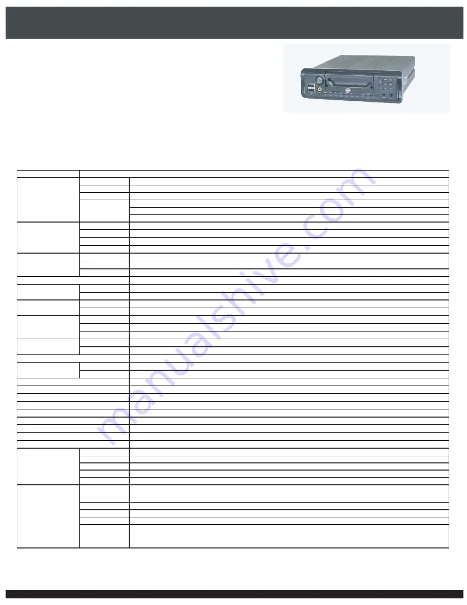
background image

-OBILE$62

DVR5104DE-HWDWF

* Pictures and specifications are subject to change without prior notice

Product Features :

Specification:

Voltage

Input : 8V~36V  / Output : 12V

Power

<25W

Protection

Current and Voltage Overload protection; Short Circuit Protection;Reverse Connection Protection
Switch ON/OFF by Time
Switch OFF after Assigned Time:0~120min.
ACC or IR Controller

Weight

<2Kg

Dimension

1DIN: 178mm x 50mm x 210mm

Material

Duralumin 

Feature

Waterproof module(optional),Bracket(optional),Removeable HDD box,anti-vibration,failure free port

Temperature

-30

 ~ +50

Build-in heating film features of high temprerature protection below 0

Humidity

5


 95

Vibration Shock

Testing Standard:GJB 150.16A-2009 and GB/T 4798.5-2007
Standard H.264 Main profile

Input

Composite

1.0Vp-p

75Ω

Air Connect×4

Output

Composite

1.0Vp-p

75Ω

Air Connect×2

ahead audio output interface

Live

720*576

PAL

㸧㸪

720*480

NTSC

Recording

704*576

PAL

㸧㸪

704*480

NTSC

Live

100fps

PAL

㸧㸪

120fps

NTSC

Recording

100fps

PAL

㸧㸪

120fps

NTSC

Playback

100fps

PAL

㸧㸪

120fps

NTSC

Input

Analog x 4

Output

Analog x 1
yes

Input

4CH(5V)

Output

2CH
8CH Car  Status Sensor (12V/24V), 1CH Speed Sensor,Display full screen rear view when reversing
Auto , when Switched on (default); Sensor/Alarm, Overspeed.
RS-232x1, RS485x1, USB2.0x2
RS-485x1, USB2.0x2
Ethernet×1

GPRS / EDGE / 3G

EVDO / TD-SCDMA / WCDMA

×1

WIFI×1

Front-panel keys,IR controller,IE/CMS
Option(Embedded)
Option(Embedded)
Option(Embedded)

Cellphone

iPhone

ipad

Android

Blackberry

Windows mobile Self-adaptive frame rate

resolution adjustable

WIFI

150Mbps

3G

WCDMA/EVDO/TD-SCDMA/EDGE

DDNS

Yes

Email

with photo in Jpeg and message

Mode

Internet Access

Ethernet,3G,PPPoE,WI-FI;support auto switch among networks;

Remote Upgrade Yes
Remote Config

yes

Car Info Manager

Work Environment

Resolution

Frame Rate

Audio

Basic

Power Supply

Mode

G-Sensor
Temperature Sensor

Car informatiom

Plate,path,company,driver,etc.

Driving status

turn left/right,front door/rear door,speed,reverse, brake,ect.

GIS:google maps or Mapinfo;display position/path/speed:playback with driving track.

Network

Client

Alarm

IE,CMS;up to 10 users  online; Support two or more user clients connection(With enough network bandwidth);
the stand-alone series support simultaneously 36ch video connection with the capbility of managing over 2000 vehicles;

Car Sensor
Recording Mode
Storage

Compression

Bidirectional Audio

I/O
Network
User Interface
GPS

Video

DVR5104DE-HWDWF

DVR5104DE-HWDWF Series DVR Adopt a Leading Design Concept of the industry, wihth dimensions of Motor industry Standards 1DIN. 
It is Equipped with GPS, G-Sensor , Temperature Monitor, Video Recording, WiFi, 3G (UMT/EVDO). 

DVR5104DE-HWDWF Series Also Benefits from Anti-Shock Advanced Technology, Waterproof and Heat Dissipation, giving an enhanced Performance in
Tough Environments.
This DVR is your Perfect choice for Long Term Vehicle Surveillance such as Bus, Trains, Taxis , Law enforcement Vehicles, Etc..  

Summary of Contents for DVR5104DE-HWDW

Page 1: ...IR controller IE CMS Option Embedded Option Embedded Option Embedded Cellphone iPhoneࠊipad㸪Android㸪Blackberry㸪Windows mobile Self adaptive frame rate㸸resolution adjustable WIFI 150Mbps 3G WCDMA EVDO TD SCDMA EDGE㸹 DDNS Yes Email with photo in Jpeg and message Mode Internet Access Ethernet 3G PPPoE WI FI support auto switch among networks Remote Upgrade Yes Remote Config yes Car Info Manager Work E...

Page 2: ...Mobile DVR User Manual For H 264 4 channel mobile digital video recorder All rights reserved ...

Page 3: ...arted for a long period of time Do not place objects on the mobile DVR Do not install the device on the intense vibration place of the vehicle like the rear Do not install this device near any source of heat such as radiators heat registers stoves or any other device that produces heat Do not expose the machine to rain or moist environment Please turn off the DVR immediately if any solid or liquid...

Page 4: ... Card and 3G SIM Card 6 2 2 3 Install Holders 7 2 2 4 MCMS Software Installation 8 2 3 Front Panel Instructions 9 2 4 Rear Panel Instructions 11 2 5 Remote Controller 12 2 6 Control with Mouse 14 2 6 1 Connect Mouse 14 2 6 2 Use Mouse 15 3 Basic Function Instruction 16 3 1 Power On Off 16 3 1 1 Power on 16 3 1 2 Power off 16 3 2 Login 17 3 3 Live Preview 17 3 3 1 Live Playback 18 4 Main Menu Setup...

Page 5: ... 2 3 Spot 24 4 2 4 Mask 25 4 3 Record Configuration 26 4 3 1 Enable 26 4 3 2 Record Bitrate 26 4 3 3 Time 27 4 3 4 Stamp 28 4 3 5 Recycle Record 28 4 4 Schedule Configuration 29 4 4 1 Schedule 29 4 4 2 Car Sensor 30 4 4 3 Join Up 30 4 5 Alarm Configuration 30 4 5 1 Join Up Alarm 30 4 5 2 Speed Alarm 32 4 5 3 Car Sensor 32 4 5 4 Video Loss 33 4 5 5 Temperature Alarm 33 4 5 6 Other Alarm 34 4 5 7 Al...

Page 6: ...1 Reset 43 4 9 2 Import Export 44 4 9 3 Block Allow list 44 5 Record Search Playback and Backup 45 5 1 Time Search 45 5 2 Event Search 46 5 3 File Management 47 5 4 Backup 47 6 Manage MDVR 49 6 1 Check System Information 49 6 1 1 System Information 49 6 1 2 Event Information 49 6 1 3 Log Information 49 6 1 4 Network Information 49 6 1 5 Online Information 49 6 1 6 Manual Alarm 49 6 2 Disk Manageme...

Page 7: ...ack 58 7 4 Configuration 59 7 4 1 Vehicle Manager 59 7 4 2 Local Configuration 59 7 4 3 Server Configuration 63 7 4 4 User Manager 63 7 4 5 Log Query 65 7 4 6 Backup 65 7 4 7 Remote Update 66 7 5 Snap 67 Appendix A FAQ 68 Appendix B Calculate Recording Capacity 71 Appendix C Compatible Devices 72 Appendix D Specifications 73 ...

Page 8: ...e vehicle or on the other places in the vehicle through installing holders Additionally this series of device are used of Aluminum alloy materials which can cool the device effectively and protect the SATA disk The independent pluggable hard driver box is much convenient for data backup and management Due to these distinctive characteristics it is widely used in taxies police cars cash trucks cont...

Page 9: ...le packaging Two record search mode time search and event search Support deleting and locking the recorded files one by one Alarm 2 channel alarm output and 4 channel alarm input available Support schedule for Join Up alarm Speed alarm Temperature alarm Car Sensor alarm etc Support pre recording and post recording Support linked channels recording once motion or alarm triggered on certain channel ...

Page 10: ...Support remote PTZ control with preset and auto cruise Support remote full menu setup changing all the DVR parameters remotely Support MCMS to manage multi devices at most 20000 on internet Support 3G PPPoE mobile network connection and150Mbps WIFI wireless connection in LAN Support Network auto switch Vehicle information management Support 3 level area configuration like city district motorcade p...

Page 11: ...enna Power cable Extension cord for IR controller Two way talk cable DIN holders U type and L type holders AV cable Alarm RS485 cable Lines to connect AV power cable 2 2 Installation 2 2 1 Install Hard Drive Notice 1 This series support one SATA hard drives Please use the hard drive the manufacturers recommend specially for security and safe field 2 Please calculate HDD capacity according to the r...

Page 12: ...he hard drive key from accessories put the key into the lock and turn it clockwise to open the HDD case Step3 Pull out of the HDD case as shown in the following left picture Step 4 Unscrew the case as shown in the right picture Step 5 Open the case Step 6 Find the square holder and mount the HDD in the holder as shown in the following right picutre ...

Page 13: ...ew them firmly Step 8 Close the top cover of the HDD case and then screw firmly with screws on the both sides 2 2 2 Install SD Card and 3G SIM Card Step 1 Pull out of the HDD case as the above mentioned steps 1 3 Then the SD card slot and SIM card slot can be seen Step 2 Find the SIM card set and put the SIM card in it Step 3 Insert SD card and SIM card into the relevant slot ...

Page 14: ...ders First find the long holders as shown in the following left picutre Next put the device into the long holders as shown in the following right picture 2 Install U type and L type Holders First find the holders as shown in the following left picture from accessories Then mount the U type holder into the car Next screw the L type holders in the both sides of the device as shown in the following r...

Page 15: ...e the spring base to fasten the device in the car The fixed methods are shown as below 2 2 4 MCMS Software Installation Step 1 Acquire the software from the DVD disk supplied by your dealer Double click Setup exe run program to enter into the welcome wizard Step 2 Click Next button in the welcome wizard to choose destination location Click browse button to choose and then click Next button ...

Page 16: ...ation Instruction Mobile DVR User Manual 9 Chapter 2 Step 3 Now user can select program folder and then click Next button Finally please click Finish button to end the installation 2 3 Front Panel Instructions ...

Page 17: ...nection the light is red RUN Indicator the work state of the device REC When recording the light is blue NET When the network of the device works the light is blue GPS When the GPS works the light is twinkling HDD When the HDD is on the light is blue SD When the SD card is on the light is blue ALARM The device is alarming the light is red ERR If the run time errors of the device occur the light is...

Page 18: ...tion port 6 HDD case lock Before opening the HDD case users need to unlock it with the key After closing the HDD case please lock it with the key 7 Fixed screw Before opening the HDD case users need to unscrew this screw 8 Direction button Move cursor in setup 9 REC Record manually 10 Menu Enter menu in live 11 ESC Exit the current interface or status 12 To confirm the choice or setup ...

Page 19: ...C signal wire 6 VGA port VGA output connect to monitor 7 GPS Connect GPS antenna 8 WIFI Connect WIFI antenna 9 3G Connect 3G antenna 2 5 Remote Controller It uses two AAA size batteries and works after loading batteries as following Step1 Open the battery cover of the Remote Controller Step2 Place batteries Please take care the poles and Step3 Close the battery cover Frequently checking defect as ...

Page 20: ... the DVR like firmware version HDD information 3 REC Button To record manually 4 Digital Button Input digital or choose camera 5 Multi Screen Button To choose multi screen display mode 6 SEARCH Button To enter search mode 7 MENU Button To enter menu 8 ENTER Button To confirm the choice or setup 9 Direction Button Move cursor in setup or pan title PTZ 10 Button To increase or decrease the value in ...

Page 21: ...ey 8 twice and then input device ID Range from 0 65535 the default device ID is 0 with other digital number 0 9 after that press ENTER button to confirm Step2 User can check the device ID by entering into System configuration Basic configuration device ID User can also set other DVR with the same device ID For convenient to operate we don t recommend user to set the device ID too long Step3 Cancel...

Page 22: ...shown in Fig2 4 It supports digitals letters and symbols input Users can change some value by the wheel such as time Move cursor onto the value and roll the wheel when the value blinks It supports mouse drag i e Set motion detection area click customized hold left button and drag to set motion detection area Set schedule hold left button and drag to set schedule time Fig 2 4 Digital Numbers and Le...

Page 23: ...esponding chapters If users don t want to setup Wizard please click Exit button to exit the Wizard setup interface A user can also start the device by pressing Power button on the remote controller 3 1 2 Power off When the vehicle stalls the device will shut off automatically User can also power off the device by using remote controller and mouse By remote controller Step1 Press Power button and t...

Page 24: ...he MDVR system User cannot do any other operations except changing the multi screen display The default user name and password is admin and 123456 For information on how to change password add or delete users please refer to 4 7 User management configuration for more details Fig 3 1 Login 3 3 Live Preview Fig 3 2 live preview interface Symbol Meaning Green Manual record Red Join up alarm or car se...

Page 25: ...ction Instruction Mobile DVR User Manual 18 Chapter 3 3 3 1 Live Playback Click Play button to playback the record Refer to Figure3 3 User can operation by clicking the buttons on the screen Fig 3 3 live playback ...

Page 26: ...the control bar at the bottom of the screen as shown in Fig 4 1 Fig 4 1 main menu toolbar To pop up the interface as shown in Fig 4 2 click Menu button Pressing MENU button on the front panel or on the remote controller can also display the main menu Then clicking Setup icon will pop up the configuration menu Fig 4 2 main menu configuration menu ...

Page 27: ...ccording to that of camera Password check If this option is enabled a user needs to input user name and password Fig 4 3 basic configuration system Show system time Display time in live Startup wizard If enabled an opening wizard with time zone and time setup information will be displayed Max online uses To set the max user number of concurrent user logins in the DVR Video output Resolution of liv...

Page 28: ...anually Step4 Click default button to reset to the default setting click apply button to save the settings click exit button to exit current interface Fig 4 4 basic configuration time date 4 1 3 DST Step1 Enter into system configuration Basic configuration DST refer to Fig 4 5 Step2 In this interface enable daylight saving time time offset mode start end month week date etc Step3 Click default but...

Page 29: ... display the vehicle information in the MCMS After finishing setup please click Apply button to save the settings Fig 4 6 basic configuration Driver Info 4 1 5 Time Off On Setup Step 1 Enter into system configuration Basic configuration Off On setup referring to Fig 4 7 a Step 2 In this interface user can enable turn on off time Please select turn off on time Enable and then set the time manually ...

Page 30: ...uration Live configuration includes four submenus live main monitor spot and mask 4 2 1 Live In this interface a user can setup camera name and adjust colors brightness hue saturation as well as contrast Step1 Enter into System configuration live configuration live interface as shown in Fig 4 8 Step2 Select camera name and click setting button to display a window as shown in Fig 4 9 Fig 4 8 live c...

Page 31: ...ure group Click button to setup the previous channel groups of dwell picture and click button to set the latter channel groups of dwell picture Step5 Click Default to reset settings click Apply to save the settings click Exit to exit current Fig 4 10 live configuration main monitor 4 2 3 Spot Step1 Enter into System configuration Live configuration Spot interface Please refer to Fig 4 11 Step2 Sel...

Page 32: ...pot 4 2 4 Mask User can setup private mask areas on the live image picture at most threes areas Please click Setting button Setup mask area Click Setting button to enter into live image Press the left mouse button and drag the cursor to set mask area referring to below picture Click Apply button to save the settings Delete mask area Select a certain mask area and left click to delete that mask are...

Page 33: ...n to save the settings click exit button to exit current interface Fig 4 13 record configuration enable 4 3 2 Record Bitrate Step1 Enter into System configuration Record configuration Record bit rate Please refer to Fig 4 14 Step2 Setup rate resolution quality encode and max bit stream Step3 Select All to setup all channels with the same parameters Step4 Click apply button to save the settings cli...

Page 34: ...ed records If the set date is overdue the record files will be deleted automatically Fig 4 15 record configuration time Step2 Select All to setup all channels with the same parameters Step3 Click default button to reset to the default setting click apply button to save the settings click exit button to exit current interface Parameter Meaning fps Range from 1 30 NTSC 1 25 PAL Resolution Support CI...

Page 35: ... Step3 Select All to setup all channels with the same parameters Step4 Click default button to reset to the default setting click apply button to save the settings click exit button to exit current interface 4 3 5 Recycle Record Step1 Enter into System configuration Record configuration Recycle record Step2 Select recycle record to enable the recycle record function It will cover the earlier recor...

Page 36: ...er to Fig 4 17 a Fig 4 17 a schedule configuration schedule Step2 Select channel and click Setup Then a dialog box will pop up as Fig 4 17 b Now a user can edit week schedule Click add button to add a certain day schedule click delete button to delete the selected schedule Copy User can copy the specify schedule to other dates Click OK button to save the settings click Exit button to exit current ...

Page 37: ...arm Other Alarm and Alarm out 4 5 1 Join Up Alarm Join Up Alarm includes three sub menus Basic Alarm Handling and Schedule Basic Step1 Enter into System configuration Alarm configuration Join up alarm Basic referring to Fig 4 18 Step2 Enable Join up alarm and set the alarm type Two option NO and NC Step3 Select all to setup all channels with the same parameters Step4 Click default button to reset ...

Page 38: ...els It will record when alarm is triggered Click OK button to save the settings click Exit button to exit the current interface To P T Z Set linked preset and cruise for alarm User can select any channel and multiple channels as linked channels Click OK button to save the settings click Exit button to exit the current interface Step4 Select all to setup all channels with the same parameters Step5 ...

Page 39: ... with Join Up Alarm Alarm handling Please refer to chapter 4 5 1 Alarm handling Fig 4 21 alarm configuration speed alarm 4 5 3 Car Sensor Car Sensor includes three sub menus Basic Alarm Handling and Schedule Basic In this interface user can enable car sensor Step1 Select Enable and type for the Name user wants to alarm For example If the Left is enabled the device will alarm when the vehicle turns...

Page 40: ...larm handling for more details Step3 User can tick off all to setup all channels with the same parameters Step4 Click default to reset to the default setting click apply to save the Fig 4 23 alarm configuration video loss setting click exit to exit current interface 4 5 5 Temperature Alarm Temperature Alarm includes two sub menus Basic and Alarm Handling Step 1 Enter into system configuration alar...

Page 41: ... a threshold value for remaining HDD space If the threshold value is reached the system will trigger the Disk Full Alarm Step 5 Click apply button to save the settings click exit button to exit current interface 4 5 7 Alarm Out Alarm out includes three sub menus Alarm out Schedule and Buzzer Alarm Out Step1 Enter into System configuration Alarm out Please refer to Fig 4 26 Step2 In this interface ...

Page 42: ...ork configuration Network Please refer to Fig4 27 HTTP port The default value is 80 Server port Communication port The default value is 6036 Step2 If the Obtain IP address automatically is selected the device will distribute IP address subnet mask gateway IP and DNS service Step3 Click TEST button to test the effectiveness of the relevant information Next click Apply to save settings Fig 4 27 netw...

Page 43: ...ork configuration sub stream Definitions and descriptions of Sub stream Parameter Meaning FPS Range from 1 25 Resolution Support CIF Quality The quality of the clients image The higher the value is the clearer the record image Six options lowest lower low medium higher and highest Encode VBR and CBR Max bit rate Range from 64 Kbps 128 Kbps 256 Kbps 512 Kbps 768 Kbps 1Mbps 2 Mbps ...

Page 44: ... or manually input IP address Step 4 Click Test to test its validity Step 5 Click Apply to save the settings Fig 4 29 network configuration WIFI setup 4 6 4 3G Network Enable 3G module by selecting 3G Enable After it is enabled the device will automatically dial up and connect Internet 3G type WCDMA and EVDO Please select it as required Dial Up Connect Point APN Connect number User name and passwo...

Page 45: ...rk configuration MCMS setup or virtual server as shown below Different routers or servers maybe have different forwarding interface Please refer to the router manual you used MCMS Domain name User can also connect MCMS through MCMS domain name Either MCMS IP or MCMS Domain name can be used to connect MCMS Please enter into MCMS interface and then click icon Next click local basic config to check D...

Page 46: ...of the PC and click OK button Then this user will be added into the user list box Click Exit button to exit the current interface Fig 4 34 add general Authority Step1 Enter into Add user authority Please refer to Fig 4 35 Note when the default value of binding PC MAC address is 0 user is not bind with the specify computer the user can log in DVR on the binding computer after set the specific bindi...

Page 47: ...assword click Exit button to exit the current interface Fig 4 35 add user authority 4 8 P T Z Configuration P T Z configuration includes two submenus serial port and advance Serial Port Step1 Enter into System configuration P T Z configuration Serial port Please refer to Fig 4 36 Step2 Select Enable and setup the value of address baud rate and protocol according to the settings of the speed dome S...

Page 48: ...g button and then a window box will pop up as shown in Fig 4 39 b User can control the dome to rotate up up left down right down left left down right and up right and stop rotating Then adjust the rotate speed and the value of zoom focus and iris of the dome Parameter Meaning Address The address of the PTZ device Baud rate Baud rate of the PTZ device Range form 110 300 600 1200 2400 4800 9600 1920...

Page 49: ...ton and then a dialog box will pop up as shown in Fig 4 40 a Click Add button to add cruise line in the list box max 8 cruise line can be added Select a cruise line and click Setup button to pop up a dialog box as shown in Fig 4 41 Fig 4 40 cruise set Fig 4 41 cruise set modify cruise line b Click Add icon to set the speed and time of preset point Select a preset point and click Delete icon to del...

Page 50: ...ing and can also adjust the rotate speed and the value of zoom focus and iris of the dome Click Start Record to record the move track of PTZ click this button again can stop recording click Start track to play recorded track click this button again can stop play b Click icon to hide the tool bar and right click can re emerge it Click icon to exit the current interface Step5 In the Advance interfac...

Page 51: ...ess segment from accessing to MDVR or admit computer users within a certain IP address segment into MDVR For example if authorized user don t want computer users within IP address segment from 196 168 000 002 to 196 168 000 004 to access to MDVR authorized user can tick off Block list and then input such IP address segment After that click Apply to save settings If authorized users want computer u...

Page 52: ...The highlight date in the calendar means have record data Step3 Select a date and press Search button Then click the time grid to set the play start time or input play record time manually The selected time match the blue grid Step4 Click Play button to playback record click the relevant buttons on the screen to do various operations Note The vertical column means hours horizontal column means cha...

Page 53: ...ation Event search refer to Fig 5 2 Fig 5 2 Search configuration event search Step2 Click Search button and then the searched event information will displayed in the event list box User can select date channel and checkmark car sensor speed alarm join up or all accordingly Step3 Double click the record file you would like to playback ...

Page 54: ...els accordingly Lock Select a file and click Lock button to lock this file After that the file cannot be deleted or covered Unlock Select a locked file and then click Lock button to unlock this file Delete Select an unlocked file and click Delete button to delete this file Step3 Select All button and then user can lock unlock or delete all files in the file management column Step4 Double click an ...

Page 55: ...e or All and then click Backup button Step4 In the backup information interface you can check the relevant information of backup files storage type save file type etc Then click Start button to start back up To playback the files plug the USB device to a PC and browse the device you will see two folders one video play and another containing video files Open the video play folder and run videoplay ...

Page 56: ...In this interface user can check record events according to set date 6 1 3 Log Information In this interface user can check relevant log information according to set date 6 1 4 Network Information In this interface user can check relevant parameters of network 6 1 5 Online Information In this interface user can check the details of the current connection of online users 6 1 6 Manual Alarm In this ...

Page 57: ...grade and then the upgrade software name will be displayed in the upgrade list box Next select that software and then click upgrade button It will upgrade automatically Please wait for a while when the system is rebooted Never cut off power during upgrading Additionally user can upgrade the device through MCMS Please refer to chapter 7 47 Remote Upgrade for the details 6 4 Logoff Click Log off ico...

Page 58: ...teps of login described as below Double click icon on the desktop and then it will pop up a login dialog box referring to Figure7 1 User can self define the user s password letters or numbers 16 characters at most The default username is SYSTEM and password is 123456 Click OK button to enter the Control Center Fig 7 1 login 7 2 Operation Interface of The Control Center The live monitor interface m...

Page 59: ...te Surveillance Mobile DVR User Manual 52 Chapter 7 control center can realize multiple tab browse and double display screens Fig 7 2 main interface of the control center The buttons instruction of control center ...

Page 60: ... are also different The status indicators of local device are listed on the left column and the status indicators of remote device are listed on the right column User could operate the current interface on Unlock status Click to maximize Control Center window Click to minimize Control Center window or revert the Control Center to original size Click to exit Control Center Users can right click on ...

Page 61: ...audio After this item is enabled the voice can be heard from live In the device list box right click a device name A shortcut menu will be shown as follows Talk Two way talk between device end and CMS client Turn off All Live Clicking this item will close all channel images of this device Device Config Click this item to configure the device remotely GPS only Select it to show the position of vehi...

Page 62: ...titude and so on Right click map to pop up the following dropdown list To remove all vehicle information click Remove Cars To display the track of the vehicle click Show Track The blue line beside the red car is its track To display full screen click Full Screen button as shown below Right click the vehicle icon and select Exit full mode to return to the original size ...

Page 63: ... MCMS Remote Surveillance Mobile DVR User Manual 56 Chapter 7 Double click the alarm information box to pop up a separate box to display the alarm type device name channel number and alarm time ...

Page 64: ...le DVR User Manual 57 Chapter 7 At the bottom of the control center lots of information will be displayed such as vehicle information longitude and latitude information driving speed direction temperature accelerated speed and so on ...

Page 65: ...e the same settings and control operations Here we take the local playback for example In the main interface of Control Center click playback icon to display the following interface Select the Record Type from available options Schedule Manual Speed Alarm Join Up Alarm Sensor Alarm Click Select Date button to select the date for the required record Click Select Channel button to select the channel...

Page 66: ...dify region name Select the region or Vehicle name and then click icon to delete region or device Note When the device is recording or previewing the region or device cannot be deleted User needs to close the record and preview and then delete them Click icon to import vehicle information 7 4 2 Local Configuration Click Local Configuration to enter local configuration interface which includes thre...

Page 67: ...n name Registration for more details In the Local Alarm Config box set Alarm Holding Time and Post alarm record time In the Log List Maintain box set the parameters for alarm and operator logs In the Other Config box user can do settings for serial port and time Fig 7 4 local basic config Users can set control center time manually or select Synchronize with PC time The PC Restart Config box allows...

Page 68: ...NS Hosts dialog box will be displayed Next create user account For example the username is bcd password is 123456 Click Create Account button to create user account MCMS Setting Application Step1 Login to MCMS interface and then click icon to enter into Local Basic Config interface Select DDNS server and input domain name and password For example DDNS server dyndns Domain name abc dyndns tv ...

Page 69: ... schedules for each channel The user can set time periods for each day of a week i Week Schedule Configuration On Local Configuration interface select Local Schedule Config tab to enter into Local Schedule Config interface Select a camera from the device list to configure the schedule and click button Select a day of the week and then drag the mouse to select a time zone The user can create multip...

Page 70: ... alarm has been linked to a Map the selected channel camera would appear the alarm state in the Map The user can also trigger recording of channels using alarm inputs From the device list select the device and configure the Alarm Input Sensor and the trigger mode This can be set to raise a PC Audio Alarm or and record channels 7 4 3 Server Configuration The customer can configure a MDVR using the ...

Page 71: ...ogin from his her account and then modify the password from User Manager The following will introduce the steps to modify the password from user login Login from the user s account In the User Manager interface click modify button and the dialogue box of modify password will pop up Input current password new password and confirm the same in the respective fields Click OK to change the password To ...

Page 72: ...hannels and Control Center Log as per the requirement Once selected click search button and the interface would search the information as per the set parameters and display the same on the screen 7 4 6 Backup Users can backup files for a date range There are two types of backups local and remote backup The former is to backup local recording files residing on the computer and the latter Remote Bac...

Page 73: ...e as shown below Fig 7 7 Remote Update Acquire the update files Tar from the supplier and store it in the computer Then enter into the Remote Update interface Click Browse button to select the update files click Refresh button to choose the updating Device click Update button to update Note The user can define the backup path as required Note Only when the WIFI function of the device is enabled an...

Page 74: ...res and save these pictures into the designated folders Select the channel that the user wants to snap pictures choose frame from 1 30 and select whether to add the title and time on live pictures Then click browse button to select the storage routine Next click Snap button and then click Save button to save the snapped pictures If the user wants to print these pictures he can click Print button F...

Page 75: ... power when testing in the lab if 12V adapter is needed please user 12V 4A adapter d If there is still problem after all above mentioned steps are checked please contact our technical supporters Q2 There is not menu output or only has live image display a The default video output of this mobile DVR is CVBS output VGA spot output has no image display Please hold down ESC key to switch the main and ...

Page 76: ...lease check the connection of hard disk cable and data cable and make sure they are well connected If still not working please unplug them and then try re plugging again b It is forced to stop because hard disk has disabled track which causes the system checking hard disk cannot skip Please re format the HDD or change another one Q8 How to input password and digital numbers The method to input pas...

Page 77: ...r Manual 70 Appendix PC Module Parameters CPU Intel Celeron 2 4G Motherboard Intel 845 HDD 80G RAM 512M VGA NVIDIA GeForce MX440 FX5200 ATIRADEON 7500 X300 OS Windows 2000 SP4 above Windows XP SP2 above VISTA DirectX 9 0 ...

Page 78: ...k 173 Lower 256k 115 Lowest 128k 56 PAL CIF 25 Highest 1M 466 Higher 768k 295 Medium 512k 235 Low 384k 175 Lower 256k 112 Lowest 128k 56 4 The calculation format is Total Recording capacity Used space per hour MB h coverage rate of hard disk recording time hour channel numbers For instance one customer uses PAL cameras set resolution to CIF video quality to Lowest frame rate to 25 fps for enabling...

Page 79: ...rd after test Brand Capacity Kingston 8G 16G 32G Compatible HDD list after test Brand Capacity Seagate Momentus 5400 6 250GB 320GB 500GB Seagate Pipeline HDTM Mini 250GB 320GB 500GB HITACHI CinemaStar C5K320 250GB 320GB 500GB HITACHI CinemaStar C5K500 250GB 320GB 500GB HITACHI CinemaStar Z5K320 250GB 320GB 500GB HITACHI CinemaStar Z5K500 250GB 320GB 500GB WD Scorpio R Blue ML320S AF2 250GB 320GB W...

Page 80: ... air connect 4 Output Analog air connect 1 ahead audio output interface 2 way audio Yes Alarm Input 4 ch 5V Output 2 ch stem node output Recording mode Auto when switched on default senor alarm over speed Communication interface RS 232 1 RS 485 1 USB2 0 2 Storage Built in 2 5 SATA interface 1 pluggable Built out SD 1 USB2 0 2 Network Ethernet 1 GPRS EDGE 3G WCDMA 1 WIFI 1 User interface Front pane...

Page 81: ...n free Mode Switch on off by time Switch off after assigned time 1 120mins Switch on off triggered by car sensor or IR controller Basic Weight 2Kg Dimension Standard 1 DIN 178mm 50mm 210mm Material Duralumin with oxygenation on surface Feature Waterproof module optional bracket optional hot plug HDD box anti vibration failure free port Work Environment Temperature 20 50 built in heating film optio...

Page 82: ...450015000002 A0 ...

Reviews: