


NOTE (1)
Four indentations, located on the female ends of pipes and fittings, are
designed to slide straight into the male ends of pipes and fittings. Orient the four pipe
indentations to match the four entry slots on the male ends of the pipe. Push the pipe
sections together. Twist-lock one section clockwise approximately one-quarter turn, until the
two sections are fully locked. The female locking lugs will not be visible from the outside on
the black pipe or fittings. Locate them by examining the inside of the female ends.
NOTE (2)
Horizontal vent runs must be supported every three feet with wall straps. All
intake air seams, including elbows, are required to be sealed with high temperature 600
O
F
rated silicone sealant or equivalent.
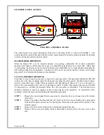
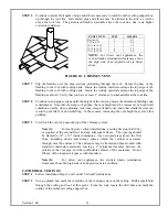
STEP 3.
With the adapter and pipe attached to the stove, slide the stove into its correct location, and mark
the wall for a 10" x 10" square hole. The center of the square hole should line up with the centerline of the
horizontal pipe. Cut and frame the 10" square hole in the exterior wall where the vent will be terminated.
If the wall being penetrated is constructed of non-combustible material, i.e. masonry block or concrete, a
7" diameter hole is fine.
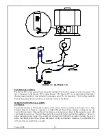
NOTE (1)
The horizontal vent must rise a 1/4" for every 1 foot of run towards from the
appliance to the termination. Never allow any vent to run downward from the stove. This
will create high temperature pockets and will create the potential for a house fire.
NOTE (2)
The location of the horizontal vent termination on an exterior wall must meet all
local and national building codes, and must not be easily blocked or obstructed.
NOTE (3)
Install a two-piece wall thimble (wall penetration heat shield) in the 10" x 10"
square hole.
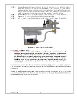
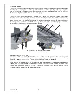
STEP 4
Position the horizontal vent termination in the center of the 10 inch square hole. Attach the
horizontal vent termination to the exterior wall with the four wood screws provided as shown
in FIGURE 13. Before attaching the Vent Termination to the exterior wall, run a bead of non-
hardening mastic around its outside edges. This mastic will provide a weather seal between
the horizontal vent termination and the exterior wall. The arrow on the horizontal vent cap
should be pointing up. Ensure that proper clearances to combustible materials are maintained
in all installations.
NOTE (1)
The four wood screws provided should be replaced with appropriate fasteners for
stucco, brick, concrete, or other types of sidings.
NOTE (2)
For buildings with vinyl sidings, a Vinyl Siding Standoff (Part 950), should be
installed between the vent cap and the exterior wall. . Attach the Vinyl Siding Standoff to the
Horizontal Vent Termination. The Vinyl Siding Standoff prevents excessive heat from
overheating the vinyl siding or the framing material underneath.
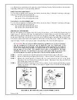
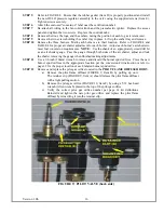
STEP 5
Before connecting the horizontal run of vent pipe to the vent termination, slide the black
decorative wall thimble cover over the vent pipe.
STEP 6
Position
the appliance and vent against the wall. Insert the vent pipe into the vent cap
assembly. It is important that the vent pipe extend into the vent cap sufficient distance so as to
result in a minimum pipe overlap of 1-1/4". Secure the connection between the vent pipe and
the cap by attaching the two sheet metal strips extending from the vent cap assembly into the
outer wall of the vent pipe. Use the two sheet metal screws to connect the strips to the pipe
section. Bend any remaining portion of the sheet metal strip back towards the vent cap, so it
will be concealed by the decorative wall thimble cover. Refer to FIGURE 14.
Version 1.0h
25
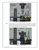
STEP 7
Slide the decorative wall thimble up FIGURE 16 to the wall surface and attach with screws
provided. Apply decorative plated trim if desired as shown in FIGURE 15.
Summary of Contents for Bayvue DV 30
Page 48: ...SAFETY LABEL Version 1 0h 47...