4
E 136 - XTA 624 C1 Eng.
22.11.10 AM
REV. 02
We reserve the right to make changes without notice
COSTER
9. WHERE TO PLACE DEVICES
9.
1
Controller
The controller should be placed in a dry environment, in compliance with acceptable environment conditions as
described under “Technical Data”. If located in environments classified as “hazardous” it should be installed in
switchboards built in accordance with applicable regulations depending on hazard class.
The controller may be installed on the board’s bottom on a DIN rail, or in DIN modular boards
9.
2
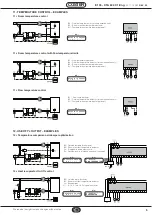
Flow temperature detector B1
B1 must be installed downstream with respect to the flow fan.
9.
3
Outside temperature detector B2
STA 001 : It may be used in systems with constant outside air inflow. It must be installed upstream with respect to
the outside air dampers near the air intake.
SAE 001 : It should be used in systems where outside air flow is not constant. It must be installed outside the bui-
lding, on the north or northwest side, at a height of at least 3 m. above the ground, protected from sunshine and
away from windows, doors, chimneys or other direct thermal interference.
9.
4
Room temperature or extract air detector B3
SAB 010 : environment : It must be installed in a spot that reflects the average temperature of a significant room
(e.g. living room) at a height of 1.5...1.6 m. above the floor, on an inside wall away from windows, doors and sources
of heat (no alcoves, scaffolds or hangings).
STA 010 : extract air: It should be installed upstream with respect to the extract fan.
9.
5
Preheating temperature detector B4
It must be installed downstream with respect to the humidifying unit, preferably downstream of the drop separator.
10. COMMUNICATION
10.
1
C-Bus communication for telemanagement
(for detailed information please see technical data sheet T 021)
XTA 624 provides :
– remote Telemanagement by when enabled by C-Bus Plug-in type ACB 400 C1
– local communication (e.g. setting via PC) when enabled with Test Plug-in ACX 232
Telemanagement is bidirectional, with one or more local PCs and/or the remote central PC via
PSTN.
Local communication is direct to a portable PC to be connected directly to the unit.
From PC or PCs it is possible to display and/or change :
– the data and values entered on display pages of the controller and those of configuration
dedicated exclusively to telemanagment (see 4.TECHNICAL DATA)
– operational status of plant components (pumps, auxiliaries in general)
– acquire alarms coming from boiler plant
– read the measurements of the detectors (temperatures : outside, flow, boiler, etc)
10.
2
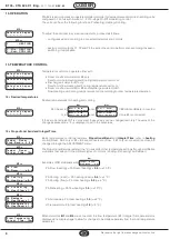
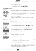
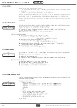
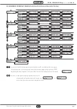
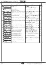
C-Bus electrical connection for local or remote Telemanagement
Each controller must be equipped with
the C-Bus Plug-in of the required type
for the controller in question
10.
3
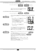
Connection to PC for local communication via test Plug-in ACX 232
Extract the C-Bus Plug-in and insert the test Plug-in ACX 232; use a standard cable to connect the RS232 plug to
the PC (the cables are included in the “CONVENIENCE KIT”.
If the PC has only USB inputs use a standard RS232 to USB conversion cable.
Observations : – Before communicating, ensure that the address entered in the controller is the address with which you wish
to communicate via PC.
– It is advisable to use a portable PC powered by battery with the connection to 230 volts unplugged, since
the earth (0 volts) of the controller is connected to that of the RS 232 and so to that of the PC. By connecting
the two earths together you could have dispersed currents, if the earths have not been well made and if the
PC has its 0 volt connected directly to the central pole of the plug (as is usual)
– The transmisssion speed can be adjusted (1200, 2400, 4800, 9600 bps).
A speed suitable for all the devices connected in C-Bus must be chosen.
ACCESSORIES:
–Test Plug-in = ACX 232
–Convenience kit = KIT RS 232
The “Convenience kit” contains
the 2 cables & other useful ac-
cessories.

